Learn how you can add Bluetooth capabilities to the iconic Billy Bass to play the audio of your choice.
The Big Mouth Billy Bass novelty talking fish is one of the weirdest toys to ever capture the American imagination. In this guide, we’ll go over how to modify the toy so that it will play and respond to any Bluetooth audio source.
Project History
I really can’t justify my stupid obsession with this talking toy fish. It’s tacky and overpriced, but for some reason, I’m consumed with putting my own spin on it.
In November of 2016, I wrote a guide on how to automatically puppet the mouth on one of these things using any audio input (including an Amazon Echo). It was a real hack job both in terms of the code and the hardware, but it has been wildly popular. People have been messaging me for an update to the guide for years, to address many of the weak points in the project — the biggest being an inability to move the mouth while also moving the head and tail.
In 2018, Amazon inexplicably partnered with the manufacturer of the Big Mouth Billy Bass to make a new, Alexa-compatible version of the toy that worked over Bluetooth. I figured this would be the end of my project’s popularity, but it turns out that the toy’s infuriatingly locked-down system was a big disappointment to many buyers. I have a whole separate video where you can learn more about the design and limitations of that product.
The silver lining of that failed product is that it created a glut of used or unsold discounted toys that are perfect for hacking.
So, in this updated version of the project, I’ve enlisted the help of my good friend Jordan Bunker and we’re going to do it right. In this guide, you’ll be hacking a Billy Bass talking fish toy so that it will respond from any Bluetooth audio source. We’ve got the mouth flapping, the head and tail flopping, and we even crammed stereo speakers inside so that everything is self-contained (no running cords out to your stereo).
Materials List
Recommended Tools
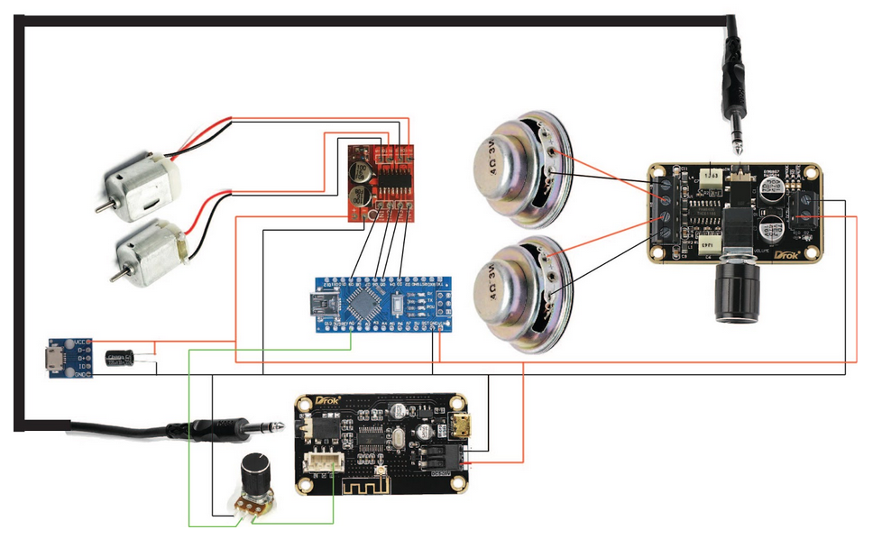
Wiring the Project
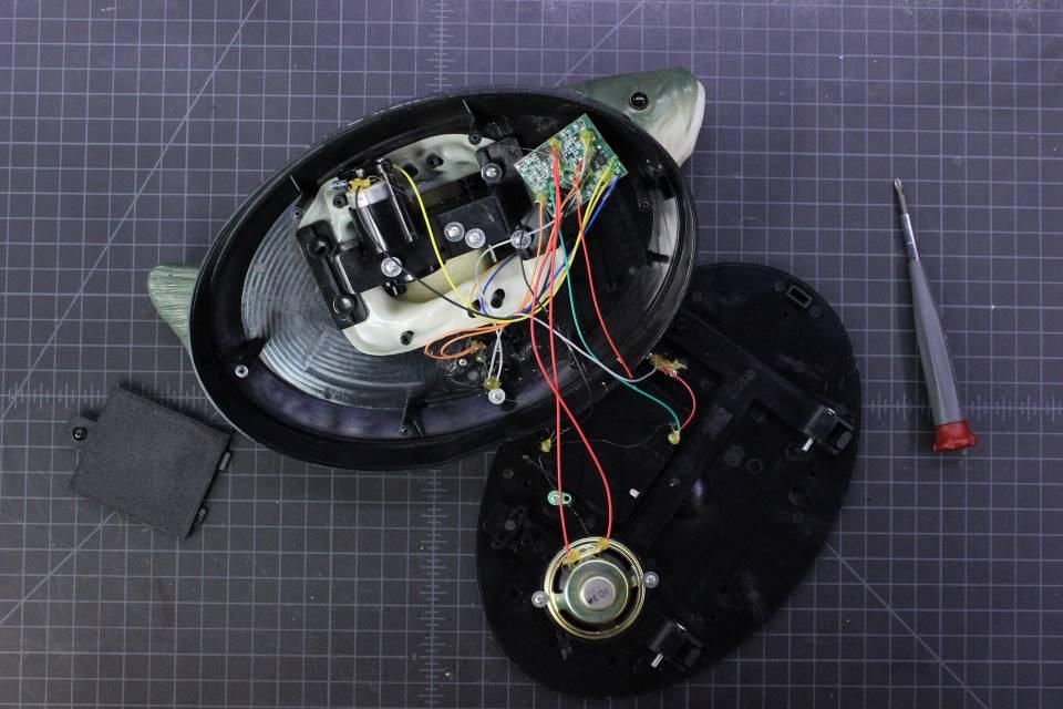
Prepare the Billy Bass
Be aware that there are a number of varying Billy Bass designs that have come out over the years. The following photos show an example of a modern generic version of the toy. The accompanying video shows one of the latest “Alexa-compatible” models of the toy (which have become the most affordable option on the used market).
Your model may look a little different inside, but because we’re essentially replacing all the internal components except for the motors, there’s no reason the following steps shouldn’t work for any Billy Bass model you have available.
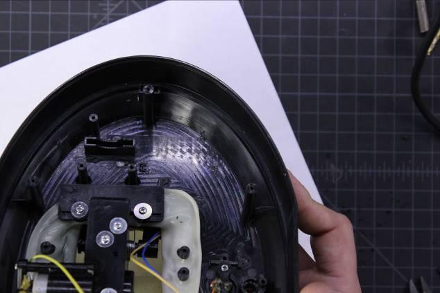
Start by removing the back of the Billy Bass to expose the board and wiring inside. If you’re working on the Alexa-compatible model, you will need a special bit to take out the screws (see Tools).
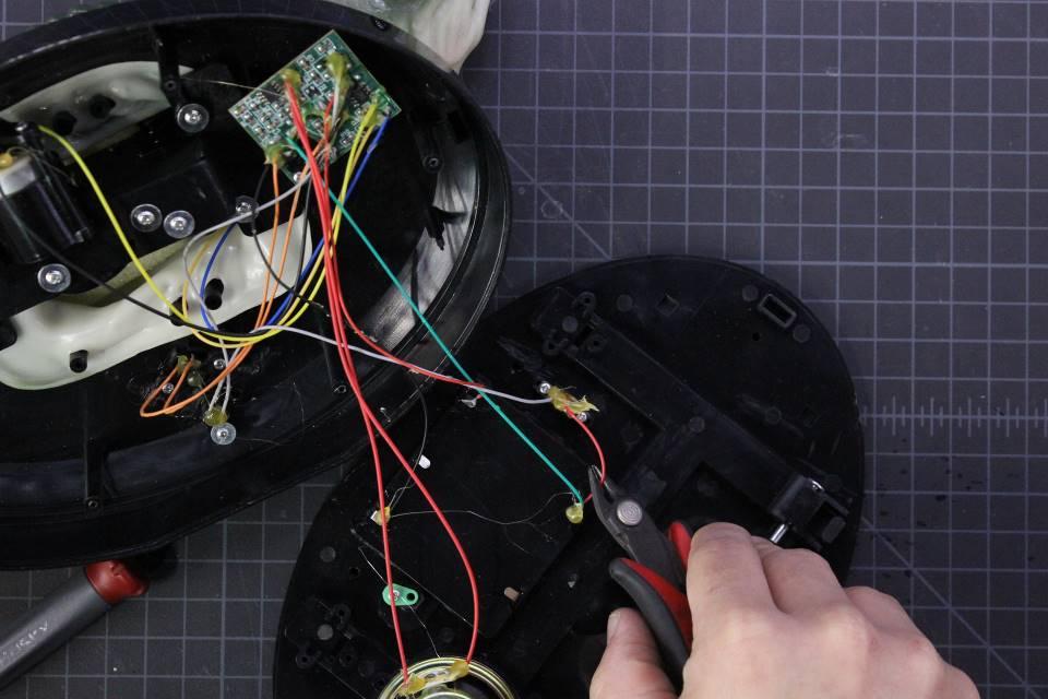
Clip the four motor wires close the board, then unscrew the board and remove it from the case. Also, clip the wires to the switch and unscrew and remove it from the case. Unscrew and remove the speaker as well.
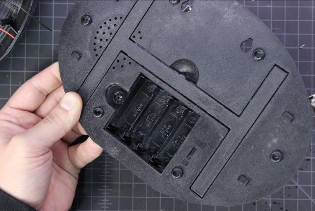
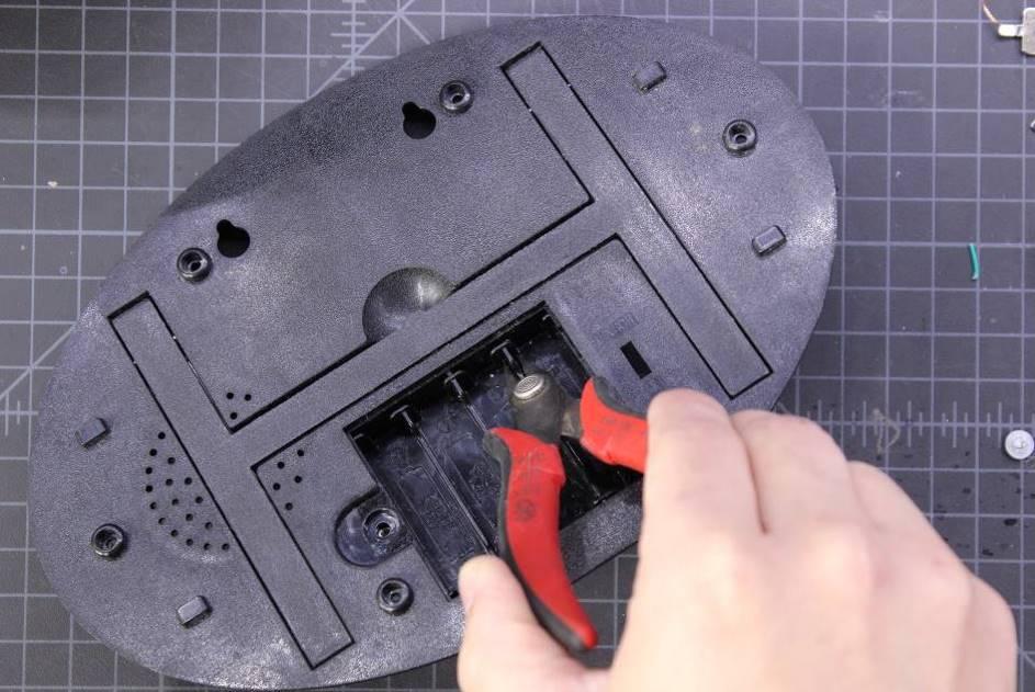
Unscrew the battery compartment lid and, using clippers and pliers, remove the wires and battery clips from the battery compartment.
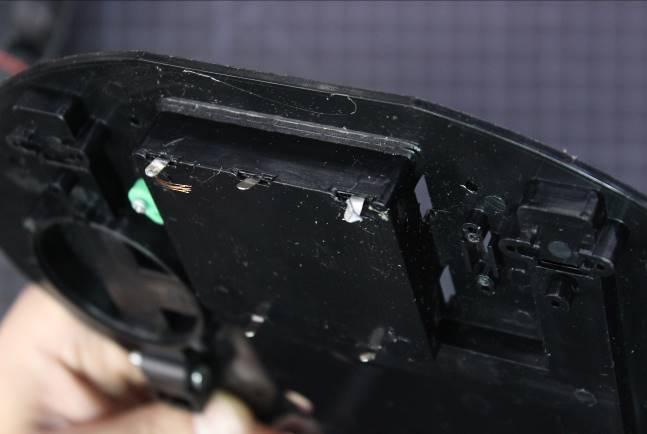
Use clippers and pliers to clip and break the dividers in the battery compartment. We’ll use this space for the Arduino and the audio input level adjustment pot later.
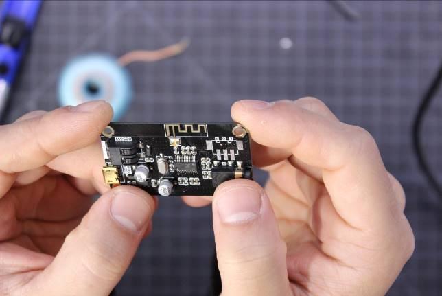
Install the Audio Components
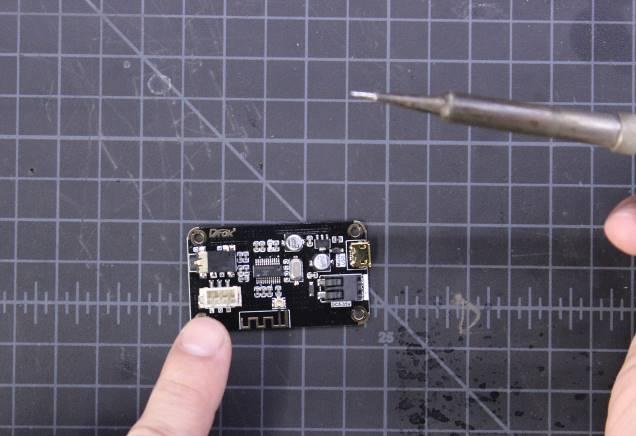
Next, desolder and remove the three pin speaker connector from the Bluetooth module. Alternatively, if you’re modifying the Alexa-compatible Billy Bass and have some JST connected wires left over from pulling out the original board and wiring, you can shave down the plastic JST connector a little and reuse the leftover wiring in this socket (saving yourself some desoldering).
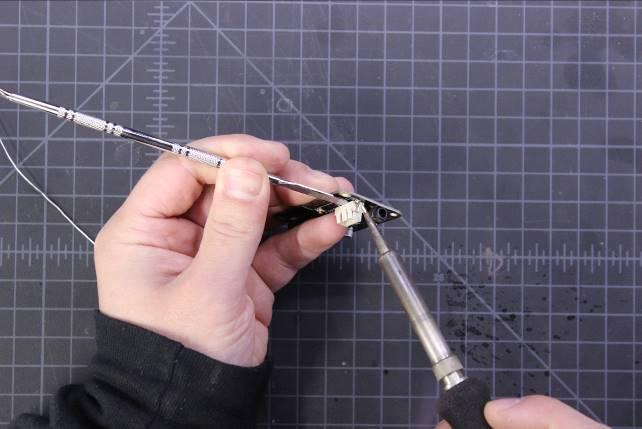
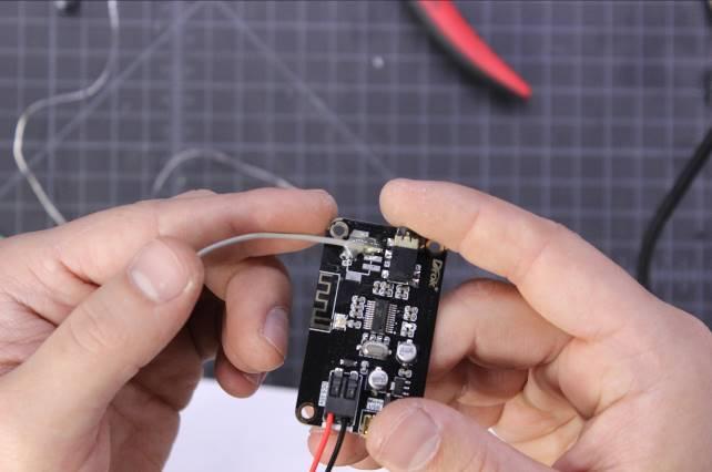
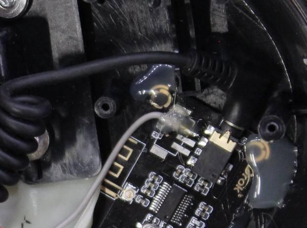
Clean the pads and connect a long wire to the L or R pad. This wire will be routed into the battery compartment of the case, so make sure it’s long enough. Secure the wire with hot glue to make sure it doesn’t break free.
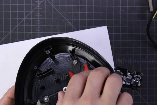
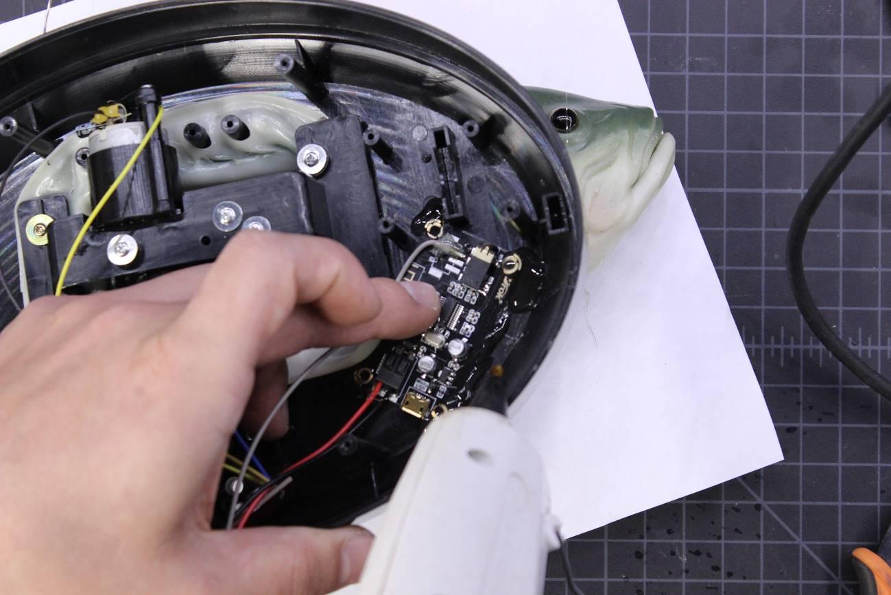
Clip off the multiple plastic standoffs in the bottom right side of the case to make a space for the Bluetooth module.
Use hot glue or double stick tape the secure the Bluetooth module in place at the bottom right of the case.
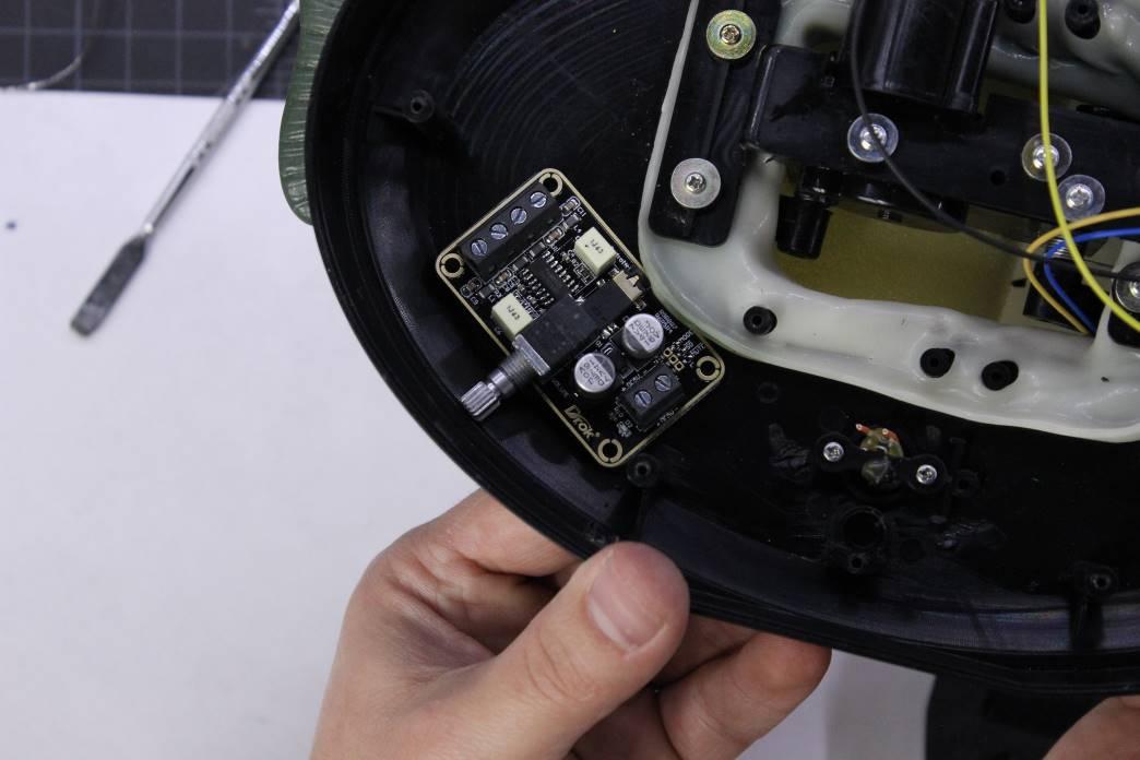
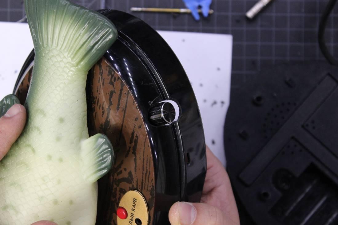
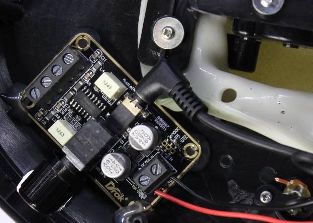
Place the amplifier module in the lower left corner and mark where the volume knob should extend outside of the case.
Use a step drill to drill a hole for the knob to fit through. Test to make sure the knob fits through the hole with the amplifier board sitting inside the case.
Use hot glue or double stick tape to secure the amplifier module in the lower left of the case.
Installing the Power Connector
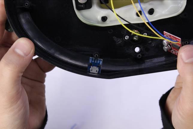
Unless you’re reusing an existing USB connection (available on the Alexa-compatible version) place the micro-USB connector board between the lower left plastic screw post and the side of the case, then mark where to make a hole in the side of the case for the cable.
Remove the board and use a drill to make a couple of holes for the cable in the marked location, cleaning up the hole with clippers and a knife as necessary. Check that the hole lines up with the board and that a cable can be inserted.
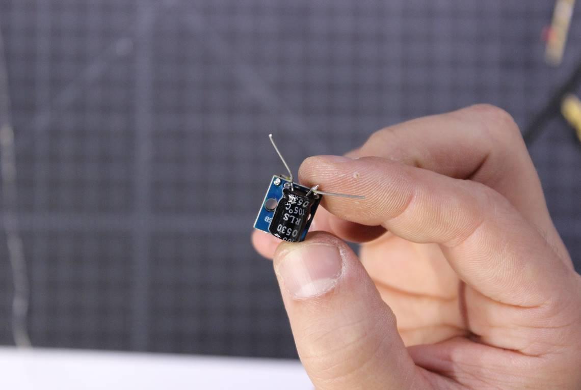
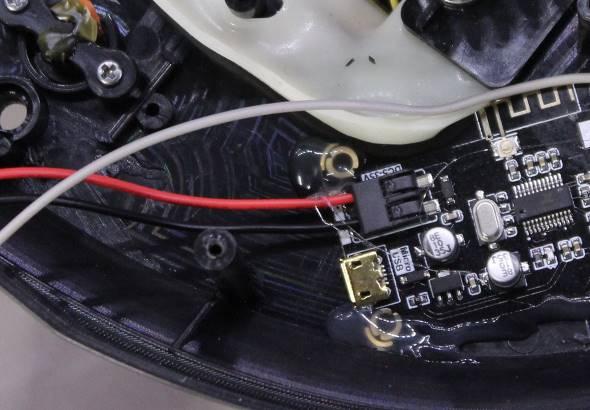
In order to keep the current draw from the motors from interrupting the operation of the Bluetooth module and amplifier, we’ll need to insert a 1000uF capacitor across the VCC and GND on the USB connector. Solder the capacitor in place, bending the capacitor against the bottom of the board and leaving enough of the leads exposed to solder wires to later.
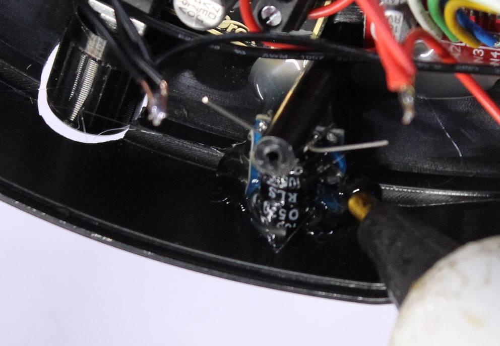
Install the board in the case, and use hot glue to secure it.
Installing the H-Bridge
Strip and solder the two wires from the body motor to Motor-A on the H-Bridge, and the two wires from the mouth motor to Motor-B.
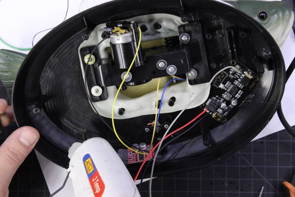
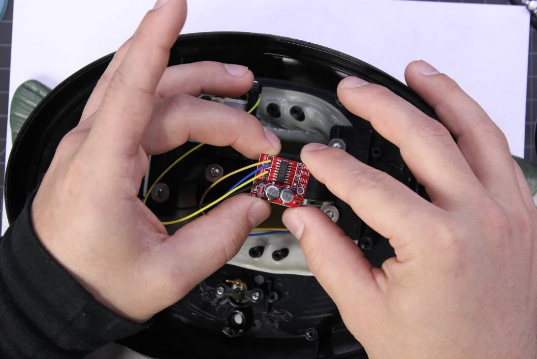
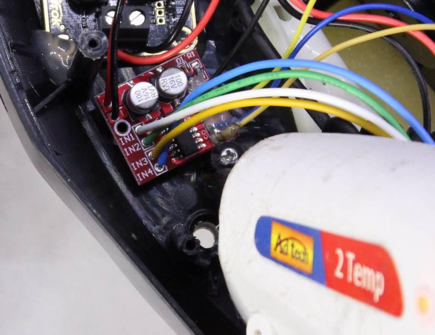
Place the H-bridge in the case between the amplifier and the red button. Estimate the appropriate length of red and black wire for power and ground from the USB connector, and solder them into the + and – holes on the H-Bridge.
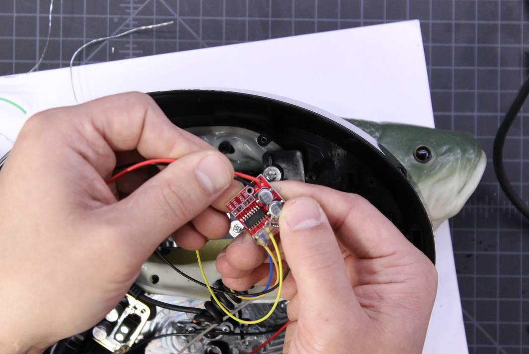
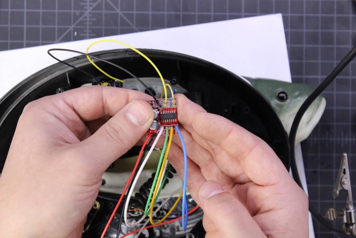
Cut four different colored wires — about five inches long each — and solder them into the four IN holes on the H-bridge. These will route to the Arduino through the battery compartment. Make note of which color connects to which input so that we can solder them to the Arduino in the correct order later.
Hot glue or double stick tape the H-Bridge into place.
Routing Power to the Components
Measure and cut the appropriate amount of red and black wire to run power and ground from the USB connector to the Bluetooth module. Then do the same for the amplifier module. Insert and secure the wires into their respective places on the boards.
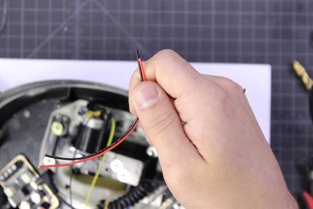
Cut about five inches of red and black wires to run power into the battery compartment to power the Arduino.
Strip the free ends of all the power and ground wires, twist them together, and solder them. Slip heat shrink over wires and then solder them to the exposed leads of the capacitor on the USB connector.
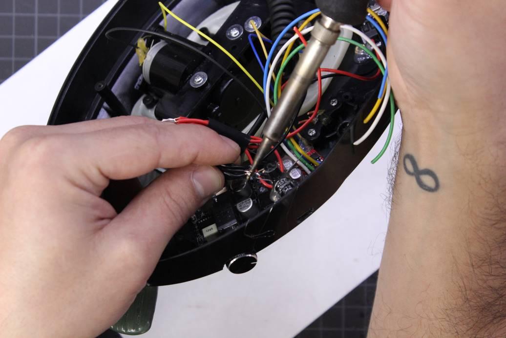
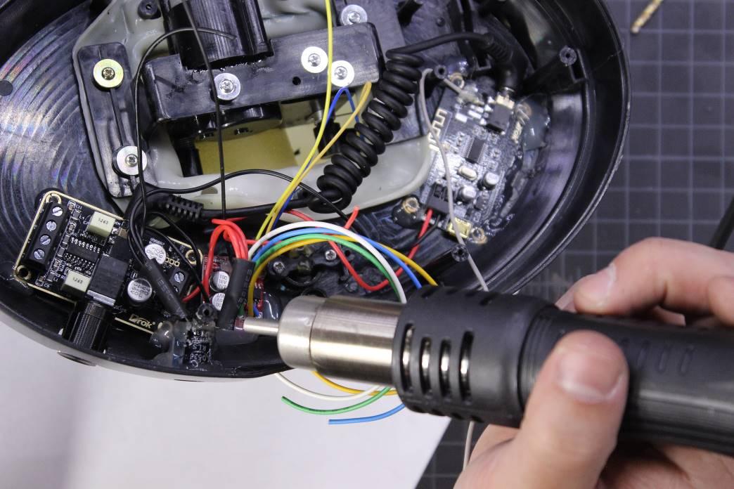
Slip the heat shrink over the exposed connections, and heat it with a hot air gun or a lighter.
Installing and Wiring the Speakers
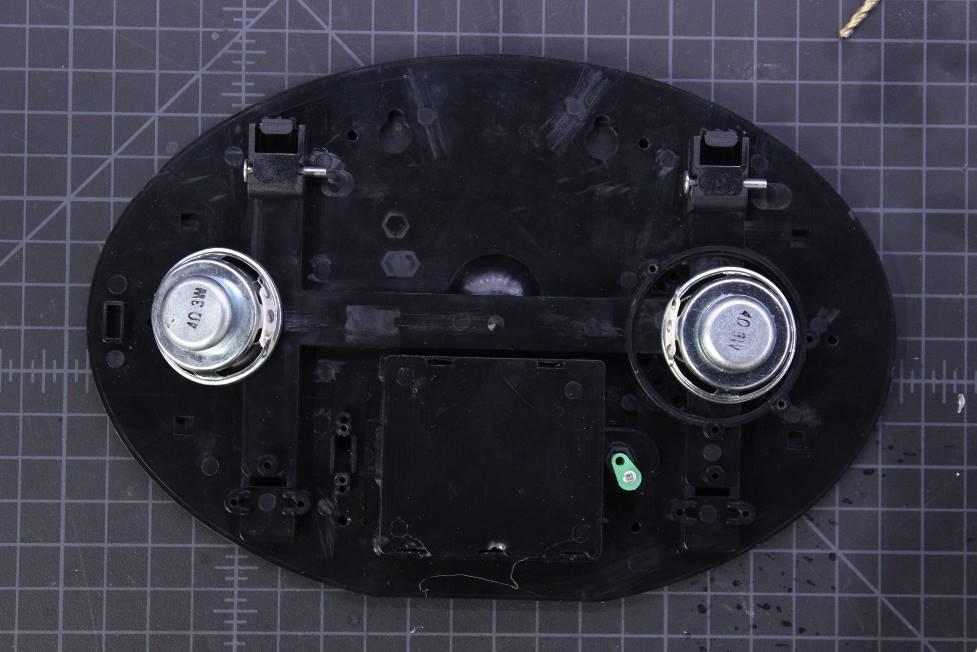
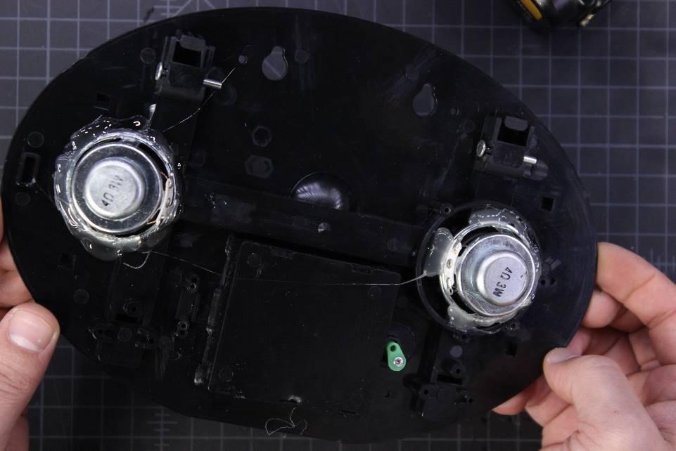
Take the back of the case and place the speakers where you want them. One of them fits where the original speaker was, but the other will have to sit partially on the raised portion of the case where the stand folds into place.
The spacing here is a bit tight, so test fit the Billy Bass onto the back case with the speakers in place. If it binds up, move the speakers and try again until you cut the case to close. If you plan on mounting your Billy Bass on the wall, then you can probably get some more room by removing the folding stand and cutting away the plastic with a rotary tool.
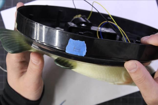
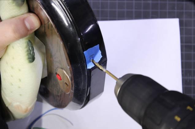
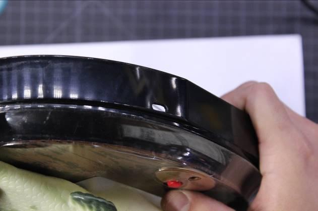
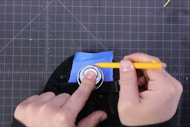
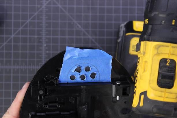
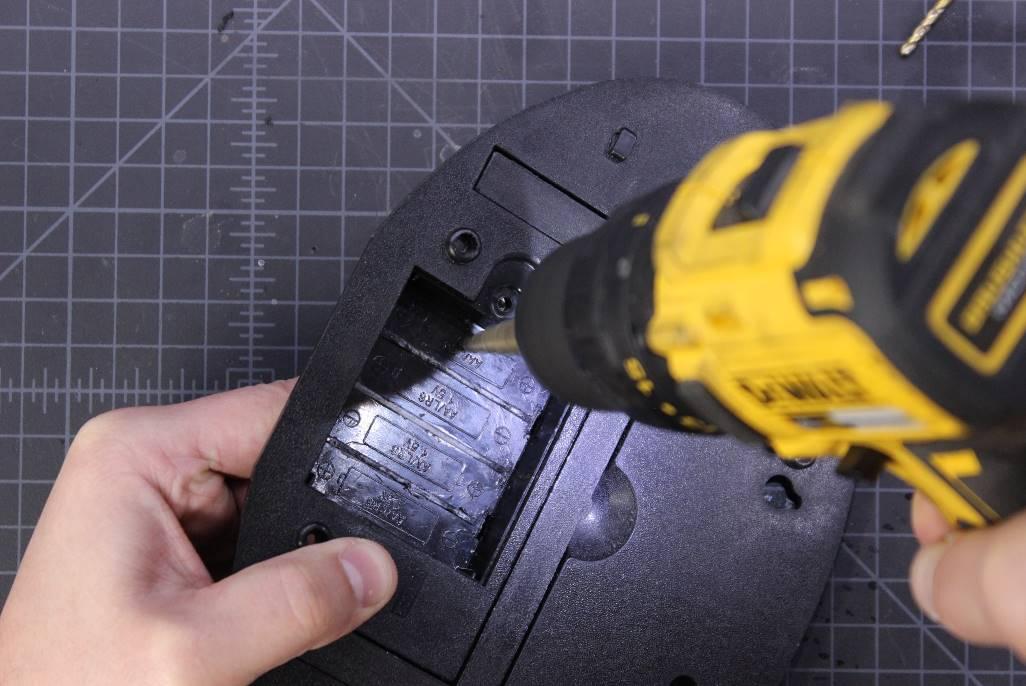
Mark where the left speaker will go and drill some holes for sound to escape through.
Use hot glue to secure the speakers in place.
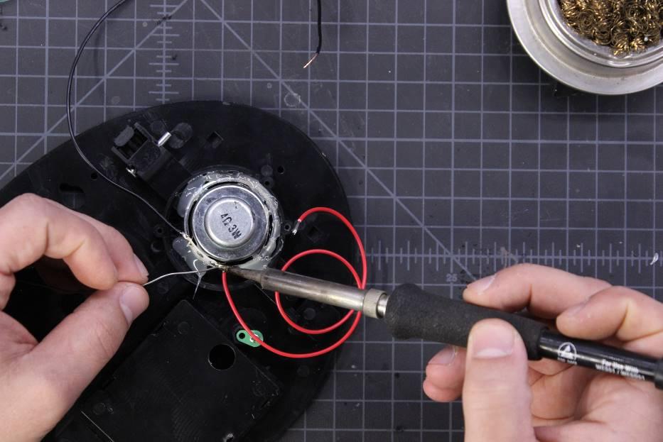
Measure, cut, strip, and solder the wires to each of the speakers. Make sure that the wires are long enough to reach the screw terminals on the amplifier board!
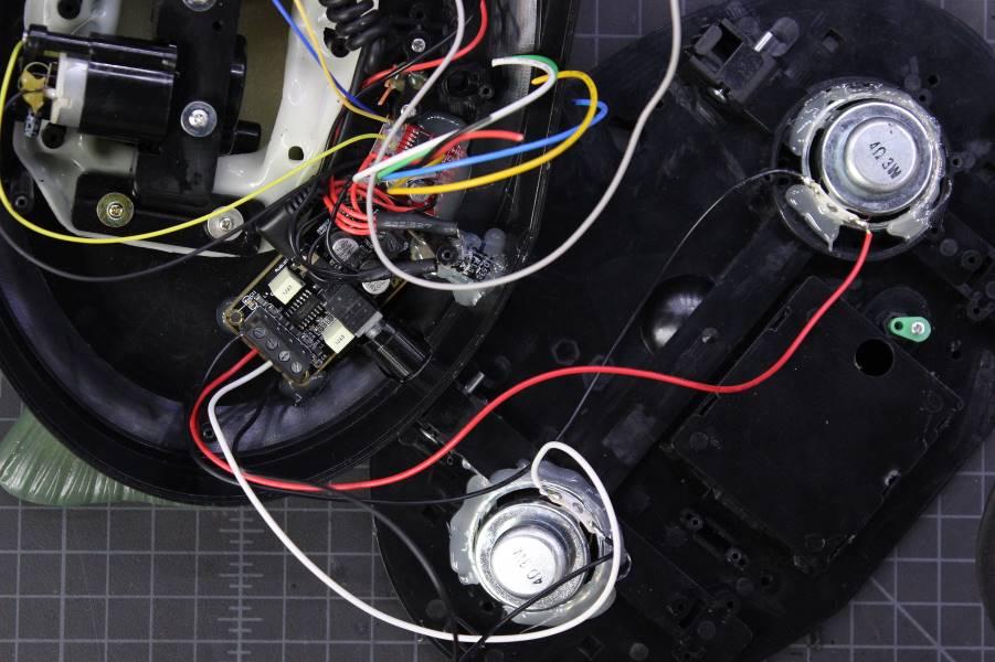
Install the wires into the appropriate terminals on the amplifier board, then do a final test fit to make sure that the case closes.
Using a short stereo TRS cable, connect the Bluetooth module to the amplifier module.
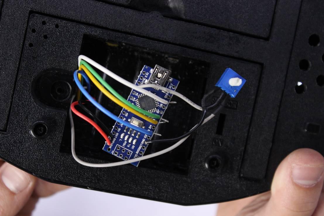
Installing the Arduino and Audio Level Potentiometer
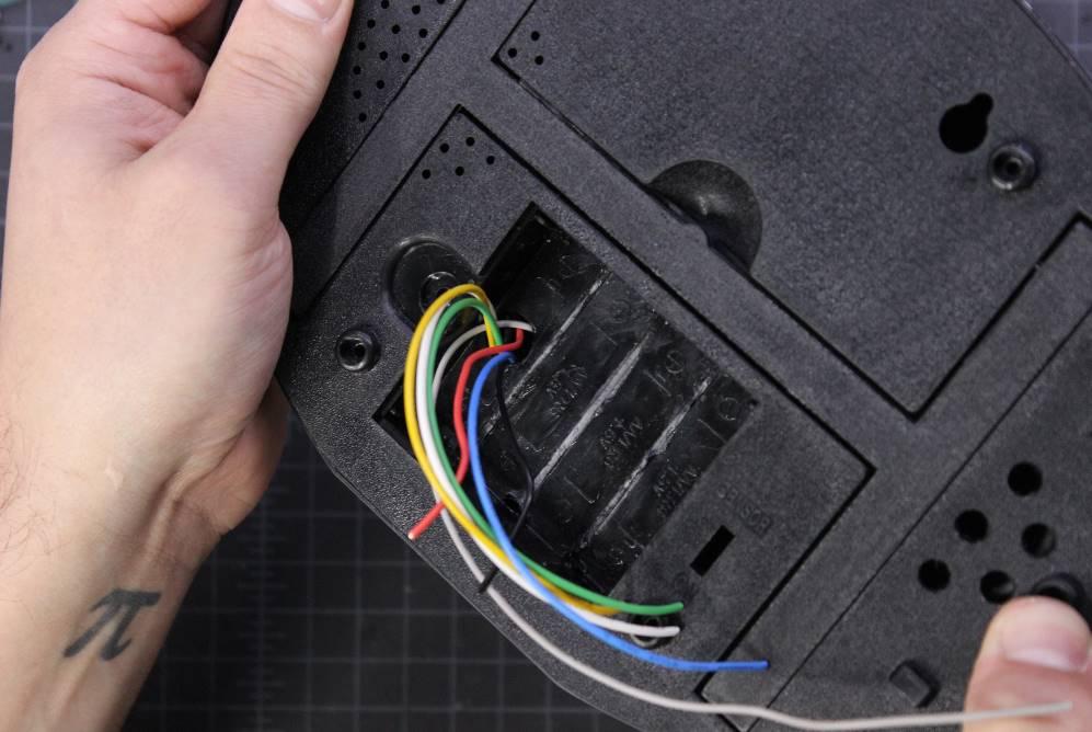
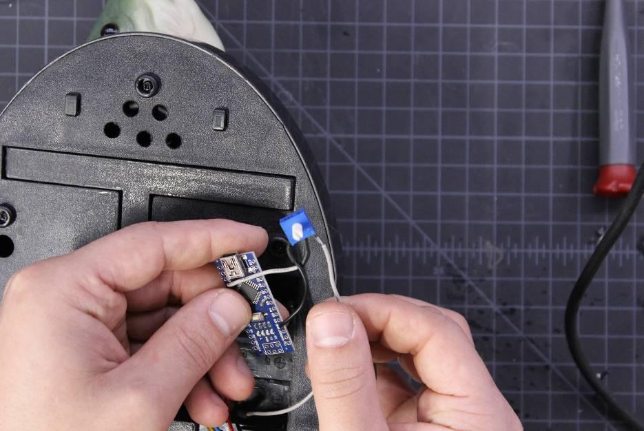
Using a step drill, drill a hole in the left side of the battery compartment that’s large enough for the power, audio, and H-Bridge wires to fit through with ease.
Carefully push the wires through the hole and screw the case back together.
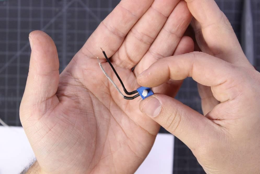
Cut two wires two or three inches long. Solder one to the left lead of the potentiometer and the other to the middle lead. Use heat shrink to keep the connections from shorting.
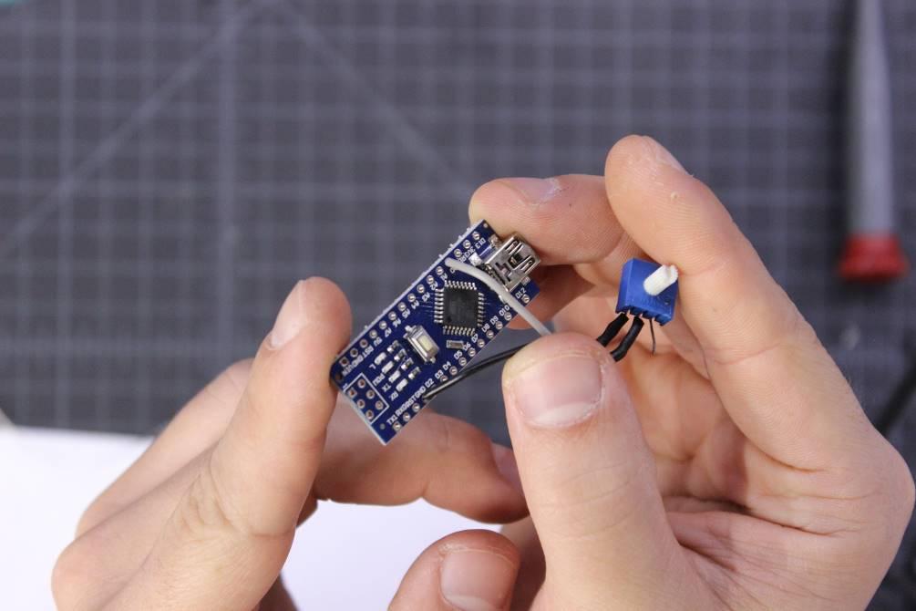
Solder the wire from the left lead of the pot to A0 on the Arduino, and the wire from the middle lead to GND on the Arduino.
Strip and solder the long audio wire leading from the Bluetooth module to the right lead of the potentiometer.
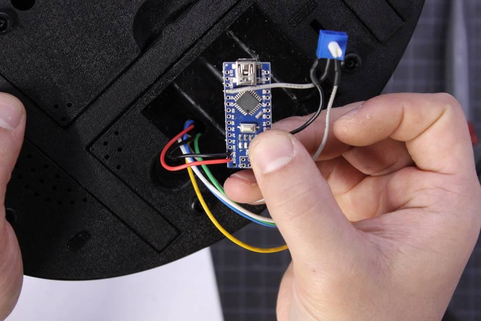
Strip and solder the red and black wires to Vin and GND on the Arduino.
Strip and solder the H-Bridge wires as follows:
- IN1 to D9
- IN2 to D6
- IN3 to D5
- IN4 to D3
We have to use pins 3,5,6, and 9 on the Arduino Nano because these pins allow us to use PWM via analogWrite.
Flash the Code and Test
Plug in USB power to the USB connector on Billy Bass, then plug the Arduino into your computer. Upload the code (which can be found on GitHub) to the Arduino, and pair your phone or computer to the Bluetooth module. Test by playing some audio and checking if the Billy Bass responds.
If either of the motor movements is backward, swap the motor pins in the code and re-upload to the Arduino. If Billy isn’t reacting to the audio peaks as much as you’d expect, or if he’s reacting too often, adjust the potentiometer in the battery compartment until you’re satisfied.
Optional Add-ons
If you want an additional line input to skip the Bluetooth module, open the case back up, and solder wires to the L, R, and GND pads on the Bluetooth module. Then run the wires to a TRS jack. Drill a hole in the side of the case, and install the jack.