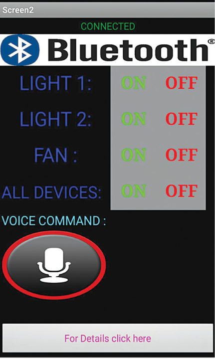
Nowadays, people have smartphones with them all the time. So it makes sense to use these to control home appliances. Presented here is a home automation system using a simple Android app, which you can use to control electrical appliances with clicks or voice commands. Commands are sent via Bluetooth to Arduino Uno. So you need not get up to switch on or switch off the device while watching a movie or doing some work.
Home automation: circuit and working
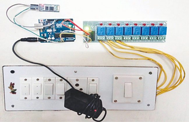
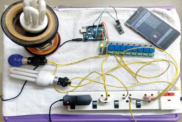
The home automation circuit is built around an Arduino Uno board, Bluetooth module HC-05 and a 3-channel relay board. The number of channels depends on the number of appliances you wish to control. Arduino Uno is powered with a 12V DC adaptor/power source. The relay module and Bluetooth module can be, in turn, powered using a board power supply of Arduino Uno. Author’s prototype is shown in Fig. 1. Connection details for each appliance are shown in Fig. 2.
Fig. 1: Author’s prototype
Fig. 2: Connections for the appliances
Bluetooth module
Bluetooth module used in this project is HC-05 (Fig. 4), which supports master and slave mode serial communication (9600-115200 bps) SPP and UART interface. Using these features it can communicate with other Bluetooth-enabled devices like mobile phones, tablets and laptops. The module runs on 3.3V to 5V power supply.
Relay module
A relay allows you to turn on or turn off a circuit using voltage and/or current much higher than what Arduino could handle. Relay provides complete isolation between the low-voltage circuit on Arduino side and the high-voltage side controlling the load. It gets activated using 5V from Arduino, which, in turn, controls electrical appliances like fans, lights and air-conditioners. An 8-channel relay module is shown in Fig. 3.
Fig. 3: Control panel on Android smartphone
String voice;
int RED = 2;
int YELLOW = 3;
void RedOn(){
digitalWrite (RED, LOW);
}
void RedOff(){
digitalWrite (RED, HIGH);
}
void YellowOn(){
digitalWrite (YELLOW, LOW);
}
void YellowOff(){
digitalWrite (YELLOW, HIGH);
}
void allon() {
digitalWrite (RED, LOW);
digitalWrite (YELLOW, LOW);
}
void alloff() {
digitalWrite (RED, HIGH);
digitalWrite (YELLOW, HIGH);
}
void setup() {
Serial.begin(9600);
pinMode(RED, OUTPUT);
pinMode(YELLOW, OUTPUT);
digitalWrite (RED, HIGH);
digitalWrite (YELLOW, HIGH);
}
void loop() {
while(Serial.available()) {
delay(10);
char c=Serial.read();
if(c=='#')
{
break;
}
voice += c;
}
if (voice.length() > 0) {
Serial.println(voice);
if (voice == "on" || voice== "all on")
{
allon() ;
}
else if (voice == "off" || voice=="all off")
{
alloff() ;
}
else if(voice =="red" || voice =="red on"){
RedOn();
}
else if(voice =="red off"){
RedOff();
}
else if(voice =="yellow" || voice =="yellow on"){
YellowOn();
}
else if(voice =="yellow off"){
YellowOff();
}
voice="";
}
}
Arduino Uno board
Arduino is an open source electronics prototyping platform based on flexible, easy-to-use hardware and software. It is intended for artists, designers, hobbyists and anyone interested in creating interactive objects or environments.
Arduino Uno is based on ATmega328 microcontroller (MCU). It consists of 14 digital input/output pins, six analogue inputs, a USB connection for programming the onboard MCU, a power jack, an ICSP header and a reset button. It is operated with a 16MHz crystal oscillator and contains everything needed to support the MCU. It is very easy to use as you simply need to connect it to a computer using a USB cable, or power it with an AC-to-DC adapter or battery to get started. The MCU onboard is programmed in Arduino programming language using Arduino IDE.
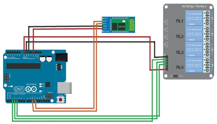
Fig. 5: Relay module connection
Pins Gnd and Vcc of the Bluetooth module are connected to Gnd and +3.3V of Arduino board respectively. Pins 2, 3 and 4 are connected to the three relays (RL1, RL2 and RL3) of the relay board. Pins Vin and Gnd of the relay board are connected to pins Vin and Gnd of Arduino board, respectively.
Note. Vin is usually used to give input power, but since we are supplying 12V to Arduino using an adaptor, we can use Vin pin on Arduino to power the 12V relay module.