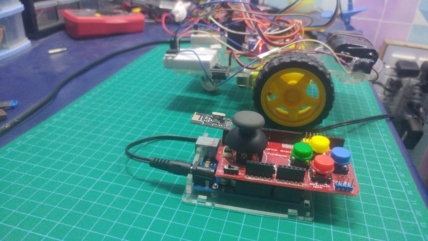
Have fun building a robot controlled by this user friendly joystick using the Funduino shield!
In this project, we are building a two-wheeled remote-controlled robot using nRF24L01 modules, a Funduino joystick shield with an Arduino UNO and Arduino nano and an L298N motor driver for controlling the DC motors.
The nRF24L01 and L298N motor driver will together be powering the bot car with the arduino nano as the brain. Moreover, for controlling this car, we are using Arduino UNO with the Funduino joystick module.
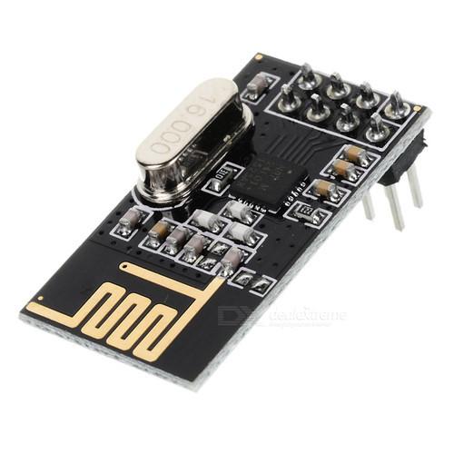
The nRF24L01 RF Transceiver Chip
The nRF24L01 is a really fast and low cost RF transceiver chip. It operates at 2.4GHz at upto 2Mbps and is ultra low power, which means that a AA/AAA battery can power it for many years. It operates at 1.9 to 3.6V supply range with a peak RX / TX current of less than 14mA.
The enhanced ShockBurstTM hardware protocol accelerator also offloads time-critical protocol functions from application microcontrollers, enable advanced and powerful wireless connectivity to low-cost, third-party microcontrollers.
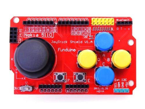
Funduino Joystick Arduino Shield
The Funduino is a really cool Arduino shield that easily fits on top of the Arduino UNO, and we can easily convert our ordinary Arduino UNO into a user-friendly joystick.
The shield provides a simple analog input with the joystick and four separate buttons. Two additional small buttons are also included.
The joystick can be used to control a variety of things such as melody, robots, or pixels on a screen and the buttons can be used for navigation or game control.
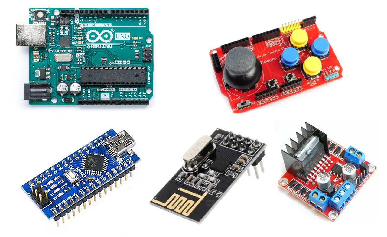
Required Hardware
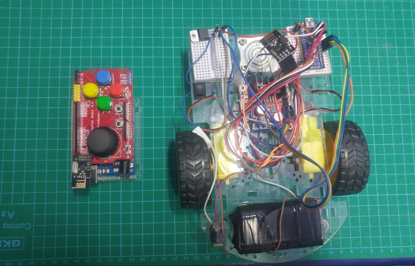
Assembling the Hardware
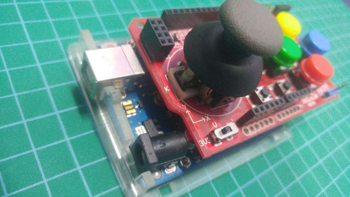
Assemble the Arduino Uno and the Funduino together.
Place the Funduino on top of the Uno. It’s very easy to assemble.
The Funduino connected to the Arduino Uno.
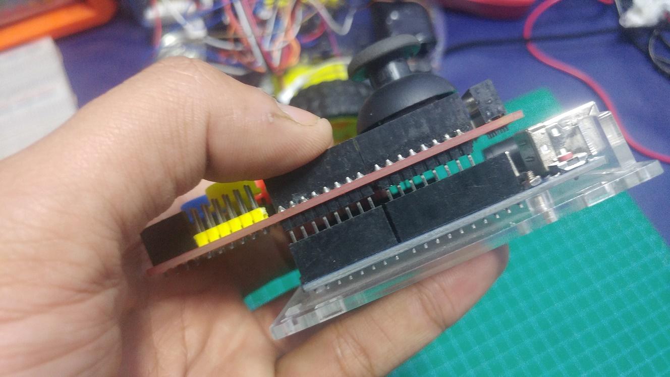
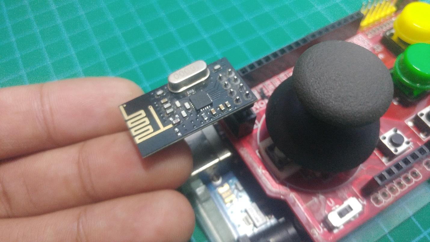
Next, insert the nRF24L01 on top of the Funduino joystick shield with the female headers as shown below.
Connect the nRF24L01 to the Funduino.
Wiring the Car
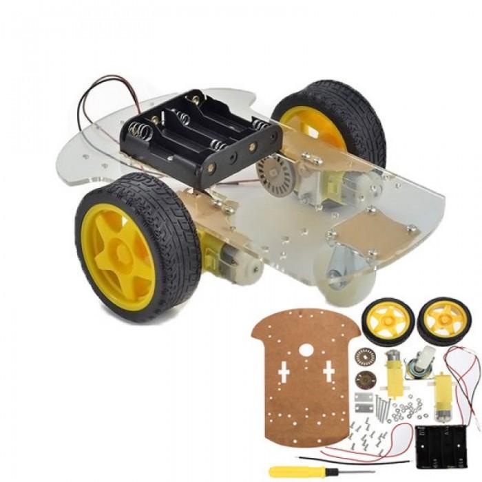
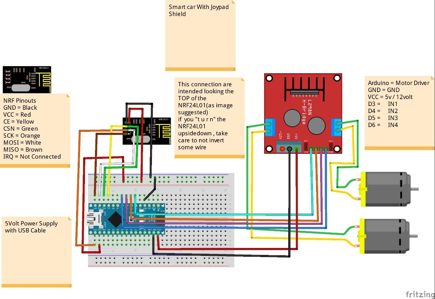
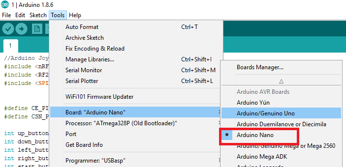
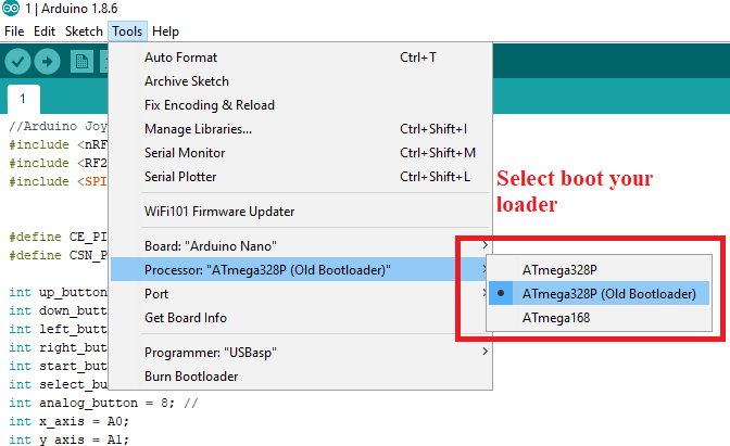
If you bought one of the robot chassis kits from Amazon, assemble it first. Next, follow the Fritzing diagram and wire everything to the Arduino Nano as shown below.
Arduino Nano | L298 |
|---|
GND | GND |
VCC | 5v/12v |
D3 | IN1 |
D4 | IN2 |
D5 | IN3 |
D6 | IN4 |
Arduno Nano | nRF24L01 |
|---|
3.3V | VCC |
GND | GND |
8 | CSN |
7 | CE |
13 | SCK |
11 | MOSI |
12 | MISO |
//Arduino Joystick shield Code
#include <nRF24L01.h>
#include <RF24.h>
#include <SPI.h>


#define CE_PIN  9
#define CSN_PIN 10

int up_button     = 2; // Boton Amarillo - A
int down_button   = 4; // Boton Amarillo - C
int left_button   = 5; // Boton Azul     - D
int right_button  = 3; // Boton Azul     - B
int start_button  = 6; // Boton F
int select_button = 7; // Boton E
int analog_button = 8; //
int x_axis = A0;
int y_axis = A1;
int buttons[]={up_button, down_button,left_button,
               right_button,start_button,select_button,analog_button};


const uint64_t pipe = 0xE8E8F0F0E1LL;
RF24 radio(CE_PIN,CSN_PIN);
char msg[20] = "";

void setup(){
     for(int i; i <7 ; i++)
     {
         pinMode(buttons[i],INPUT);
         digitalWrite(buttons[i],HIGH);
     }
     Serial.begin(9600);
     radio.begin();
     radio.openWritingPipe(pipe);
}

void loop(){

      if(digitalRead(up_button)==LOW)
      {
        char msg[]="up";
      radio.write(&msg,sizeof(msg));
      delay(300);
        Serial.println("UP Button Pressed");
      }

       if(digitalRead(down_button)==LOW)
       {
        char msg[]="down";
      radio.write(&msg,sizeof(msg));
      delay(300);
        Serial.println("Down Button Pressed");
      }
       if(digitalRead(left_button)==LOW)
      {
        char msg[]="left";
      radio.write(&msg,sizeof(msg));
      delay(300);
        Serial.println("Left Button Pressed");
      }
       if(digitalRead(right_button)==LOW)
       {
        char msg[]="right";
      radio.write(&msg,sizeof(msg));
      delay(300);
        Serial.println("Rigth Button Pressed");
      }
       if(digitalRead(start_button)==LOW)
       {
        char msg[]="start";
      radio.write(&msg,sizeof(msg));
      delay(300);
        Serial.println("Start Button Pressed");
      }
       if(digitalRead(select_button)==LOW)
       {
        char msg[]="select";
      radio.write(&msg,sizeof(msg));
      delay(300);
        Serial.println("Select Button Pressed");
      }
       if(digitalRead(analog_button)==LOW)
       {
        char msg[]="analgobut";
      radio.write(&msg,sizeof(msg));
      delay(300);
        Serial.println("Analog Button Pressed");
      }
      Serial.print("\n X = "),Serial.print(analogRead(x_axis)),Serial.print(" \n Y = "), Serial.print(analogRead(y_axis));
      Serial.print("  ");
      delay(500);
}
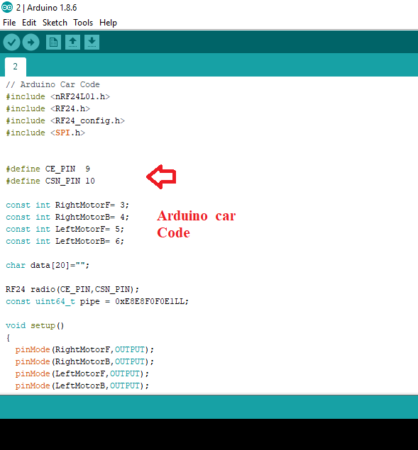
// Arduino Car Code
#include <nRF24L01.h>
#include <RF24.h>
#include <RF24_config.h>
#include <SPI.h>


#define CE_PIN  9
#define CSN_PIN 10

const int RightMotorF= 3;
const int RightMotorB= 4;
const int LeftMotorF= 5;
const int LeftMotorB= 6;

char data[20]="";

RF24 radio(CE_PIN,CSN_PIN);
const uint64_t pipe = 0xE8E8F0F0E1LL;

void setup()
{
  pinMode(RightMotorF,OUTPUT);
  pinMode(RightMotorB,OUTPUT);
  pinMode(LeftMotorF,OUTPUT);
  pinMode(LeftMotorB,OUTPUT);
  Serial.begin(9600);
  radio.begin();
  radio.openReadingPipe(1,pipe);
  radio.startListening();
}

void loop(){
  String msg="";
  if ( radio.available() )
  {
    radio.read( data,sizeof(data) );
    Serial.println(data);
    msg=data;

    if(msg=="up")
    {
  digitalWrite(RightMotorB,LOW);
  digitalWrite(LeftMotorB,LOW);
  digitalWrite(RightMotorF,HIGH);
  digitalWrite(LeftMotorF,HIGH);
  Serial.println("Motor forward");
  }
  else if(msg=="down")
  {
  digitalWrite(RightMotorB,HIGH);
  digitalWrite(LeftMotorB,HIGH);
  digitalWrite(RightMotorF,LOW);
  digitalWrite(LeftMotorF,LOW);
  Serial.println("Motor Back");
  }
   else if(msg=="left")
  {
  digitalWrite(RightMotorB,LOW);
  digitalWrite(LeftMotorB,HIGH);
  digitalWrite(RightMotorF,HIGH);
  digitalWrite(LeftMotorF,LOW);
  Serial.println("Left");
  delay(300);
  digitalWrite(RightMotorB,LOW);
  digitalWrite(LeftMotorB,LOW);
  digitalWrite(RightMotorF,LOW);
  digitalWrite(LeftMotorF,LOW);
  }
   else if(msg=="right")
  {
  digitalWrite(RightMotorB,HIGH);
  digitalWrite(LeftMotorB,LOW);
  digitalWrite(RightMotorF,LOW);
  digitalWrite(LeftMotorF,HIGH);
  Serial.println("right");
  delay(300);
  digitalWrite(RightMotorB,LOW);
  digitalWrite(LeftMotorB,LOW);
  digitalWrite(RightMotorF,LOW);
  digitalWrite(LeftMotorF,LOW);
  }
  else if(msg=="analgobut")
  {
  digitalWrite(RightMotorB,LOW);
  digitalWrite(LeftMotorB,LOW);
  digitalWrite(RightMotorF,LOW);
  digitalWrite(LeftMotorF,LOW);
  Serial.println("STOP it");
  }

  }
}
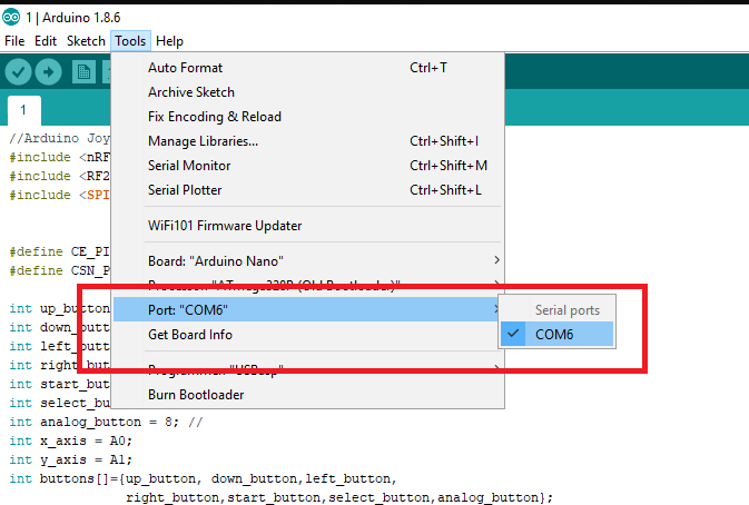
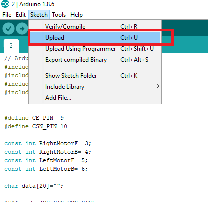
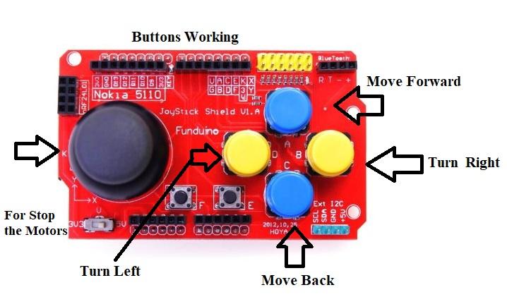
Testing the Funduino
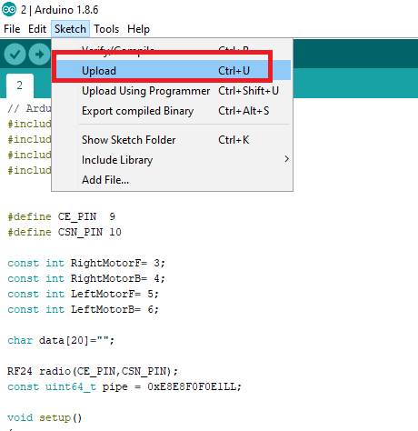
After uploading the code for both the remote and the car, it’s time to test it! Here are the controls for the car: