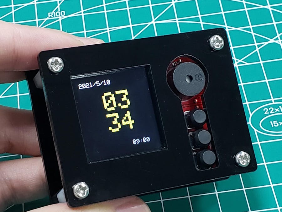
This project shows how to DIY a smart clock. I can experience the fun of soldering and assembling from this project. Surprisingly, I can complete the WiFi connection without loading the code. Besides the clock and alarm, check the weather in different cities and set the different time zones.
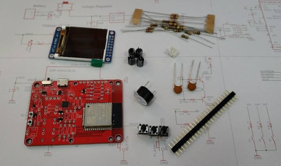
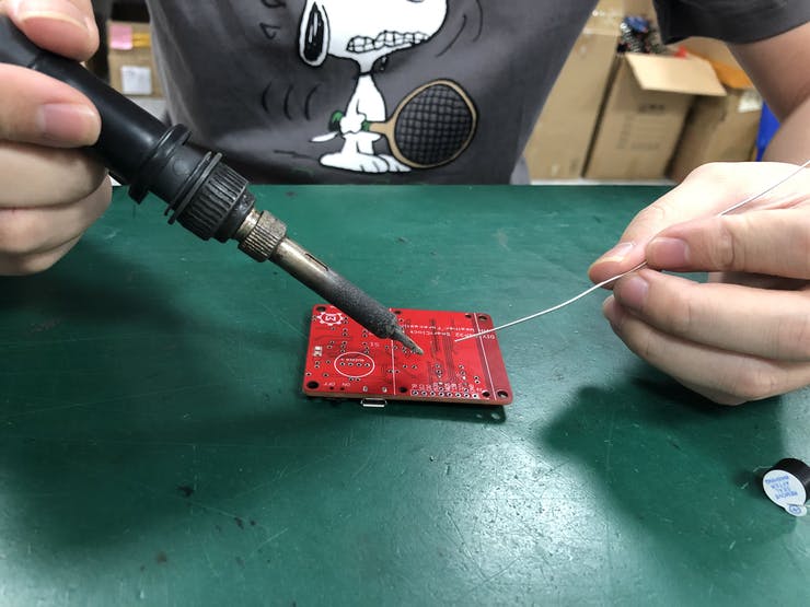
Start the soldering by inserting the electronic component into the pads of the circuit board, The order of the component to solder is determined by the high of the component It is highly recommended to insert resistors in the pads and solder them firstly. When the lower height component (as a resistor) has been welded, they will not hinder the soldering of other components (such as a capacitor). After the low components are inserted, follow the below steps to solder them and cut out the extra lead.
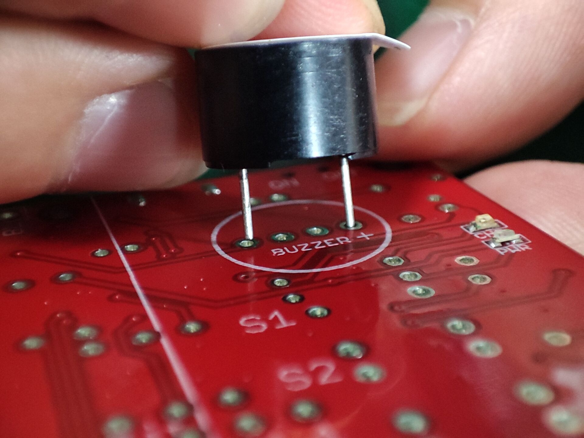
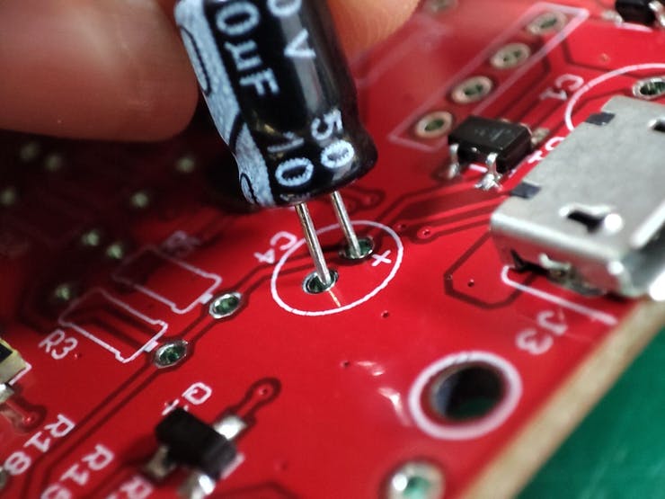
Note that the electrolytic capacitor and buzzer are polar. Refer to the polarity marking and on-board marking to insert the component, as the picture.
- Hold the soldering iron like a pen and near the basic of the soldering iron. Don’t touch the iron anywhere when the soldering is on or hot.
- Placed the soldering iron to the stand when the soldering iron is idle.
Below shows how to solder one lead of the electronic component (such as the resistor)
- Begin by inserting the lead into the hole of the circuit board.
- Turn on your soldering iron and let it heat up.
- Hold the soldering iron in one hand and solder in the other.
- Touch the tip of the soldering iron to the copper pad and the resistor lead. Hold the soldering iron in place for seconds to heat the connection. Both parts that are being soldered have to be hot to form a good connection.
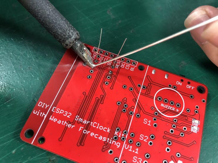
- Touch the solder to the joint, not the soldering iron directly.
- Remove the soldering iron and let the solder cool down naturally.
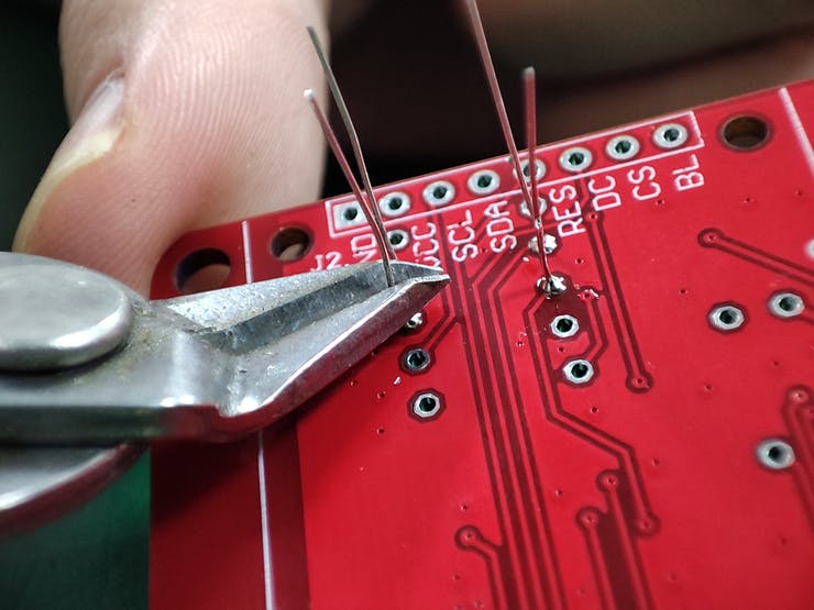
- Cut down the excess pinout.
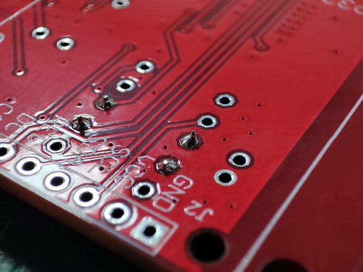
- A proper solder joint is smooth, shiny, and looks like a volcano or cone shape.
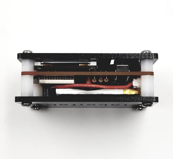
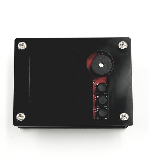
There are acrylic shells and screws/ stands to package the PCBA and battery.
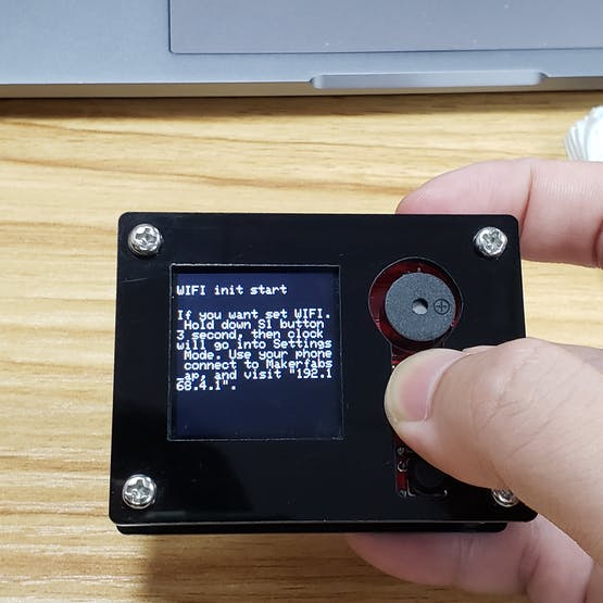
- When turning the power button on, press the button(top) and hold it in 1S;
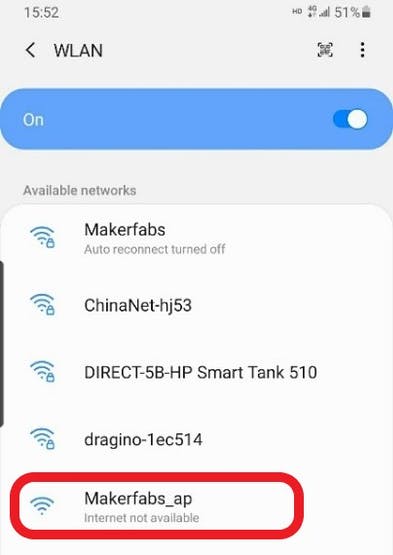
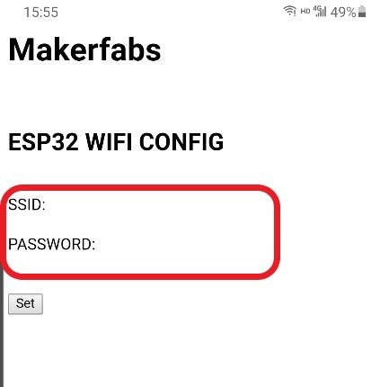
- Release the top button, use a mobile phone or PC to connect the WiFi “Makerfabs_ap”.
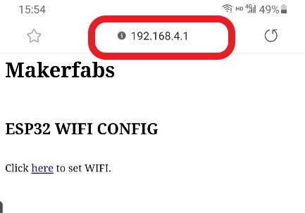
- Type the IP “192.168.4.1” to Chrome or other browsers on your phone to enter the server.
- Input your WiFi credentials to the server, ESP32 will connect to WiFi after a minute.
- As the WiFi connection set finished, it will record the setting and connect the WiFi automatically. If the WiFi settings need to be updated, follow the above steps to retype WiFi credentials again.
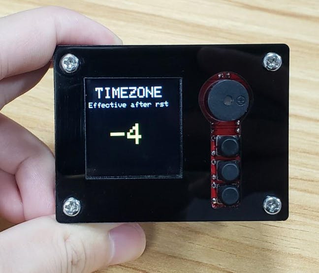
- Press the top button to change the page to time zone setting.
- Press the bottom button to modify the time zone you want.
- When you finish the change, reset the board and the settings would take effect.
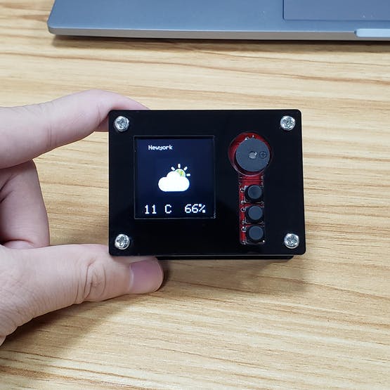
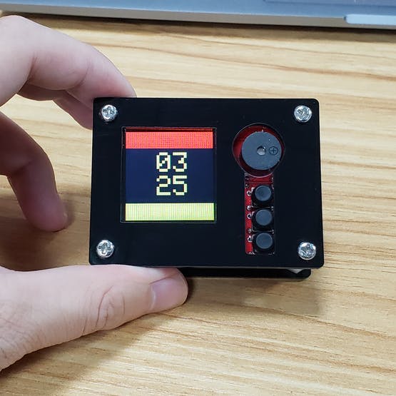
- Press the top button to change the clock page, the LCD will show the local weather, temperature, and humidity.
- You can press the bottom button to navigate the cities you pre-set in the firmware.
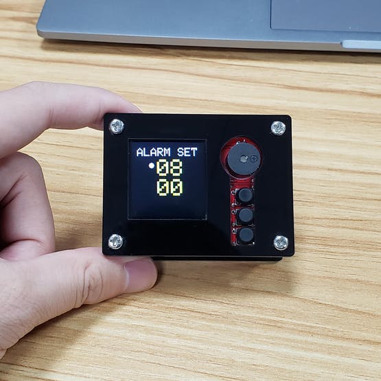
- Press the top button to change the page to Alarm setting.
- Press the middle button to select the hour or minute.
- Press the bottom button to add one to the value.
- When the alarm is ringing, press any button to pause it.