Learn to make a photography exposure meter using an Arduino UNO and the BH150 sensor module.
In this tutorial, I show you how to make an exposure meter using an Arduino UNO, an SSD1306 SPI OLED display, and a BH1750 sensor module.
If you shoot photos using film cameras, you can use this tutorial to build your own exposure meter to carry around in your camera bag. The meter can also come in handy for portrait photography as you always need good light to best capture the subject. BH1750 sensor results may not be 100% accurate, but it’s worth the price.
What is an Exposure Meter?
In analog photography, people used to use exposure meters all the time to measure the light respective to their film’s ISO.
For DSLRs nowadays, everything is digital and built-in. The exposure meter is basically an instrument for measuring the amount of light falling on an object or being reflected from a subject. This sensor collects the data and converts the measurement into usable information which then informs the shutter speed and aperture size required to take good photographs.
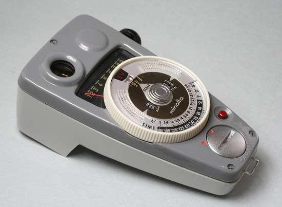
Example of a typical exposure meter
Exposure meters are widely used in the field of scenic design and cinematography in order to set the optimum lighting for a scene. They are also used in architectural lighting design and come in handy if you want to grow non-seasonal plants with the right amount of light.
BH1750 Digital Light Sensor
The BH1750 digital light sensor works via an I2C bus interface. It is mostly used in mobile phones to automatically adjust the LCD and keypad backlight. This sensor has a sensing range from 1 to 65535 lx.
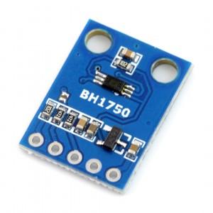
The BH1750 digital light sensor.
BH1750 Specs
- Low current consumption
- 50hz-60hz noise reject feature
- I2C communication
- Illuminance to Digital Converter
- Wide range and high resolution (1-65535 lx)
DIY Exposure Meter Capabilities
Digital exposure meters are really expensive in the market, while analog meters are not super accurate and are inconvenient to use. This led me to build my own meter for under $7, which can be powered using a normal battery bank. The meter is capable of doing the following:
- Ambient light sensing
- ND filter correction
- Aperture priority
- ISO range from 8 to 4 000 000
- Light reading in Lux.
- Flashlight metering
- Displaying exposure value, EV
- Aperture range from 1.0 to 3251
- Shutter speed range from 1/10000 to 133 sec
- Shutter speed priority
- ND Filter range ND2 – ND8192
Required Hardware
- Arduino UNO
- Pushbuttons (4)
- Breadboard
- SSD1306 SPI OLED
- BH1750 module
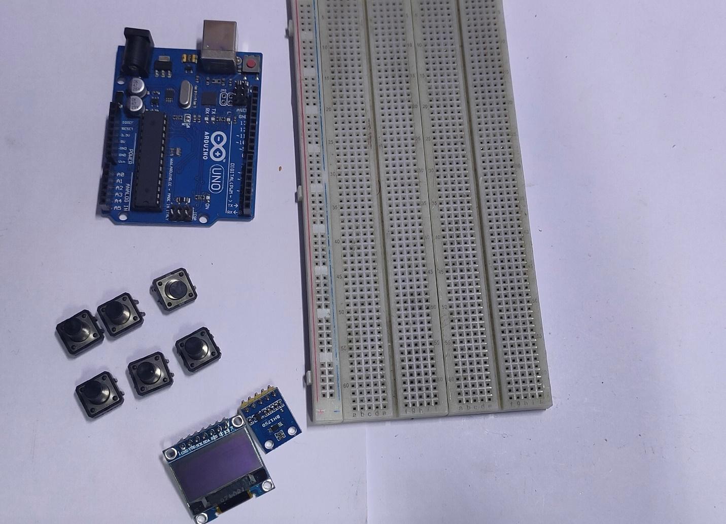
All of the required hardware.
Wiring the Hardware
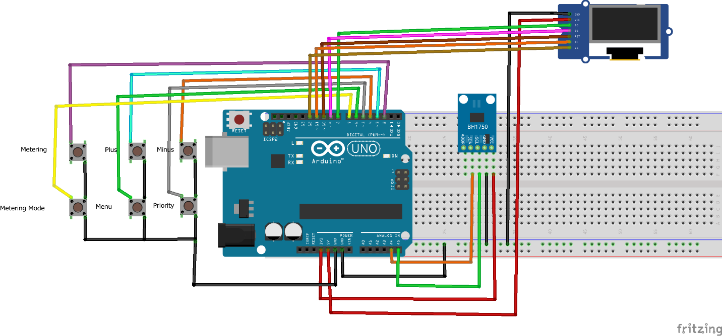
Wire up everything as shown below in the Fritzing diagram. If you are using a different version of Arduino, follow the pin to pin information given below.
Pushbutton | Arduino UNO pin |
|---|
1 - Metering | 2 |
2 - Plus | 3 |
3 - Minus | 4 |
4 - Metering Mode | 5 |
5 - Menu | 6 |
6 - Priotity | 7 |
OLED SPI | Arduino UNO |
|---|
GND | GND |
VCC | 5V |
D0 | 8 |
D1 | 9 |
RST | 10 |
DC | 11 |
CS | 12 |
BH1750 | Arduino UNO |
|---|
VCC | 3.3V |
GND | GND |
SDA | A4 |
SCL | A5 |
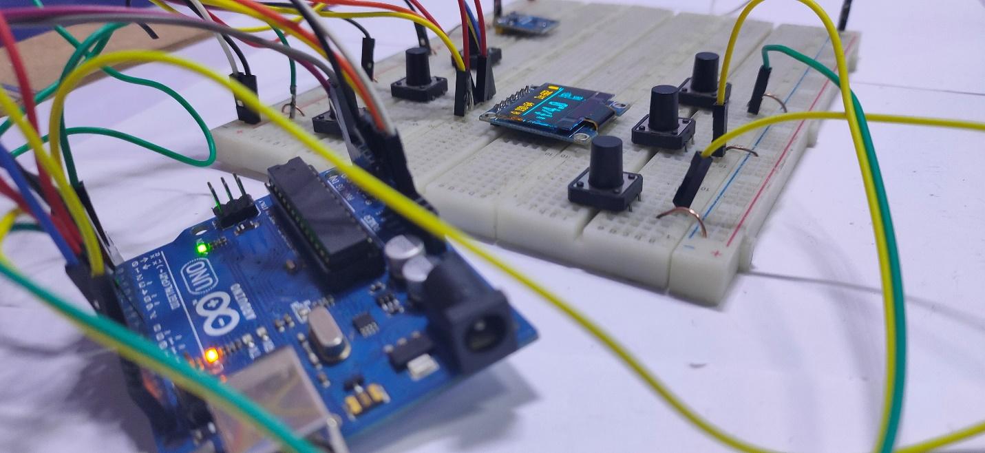
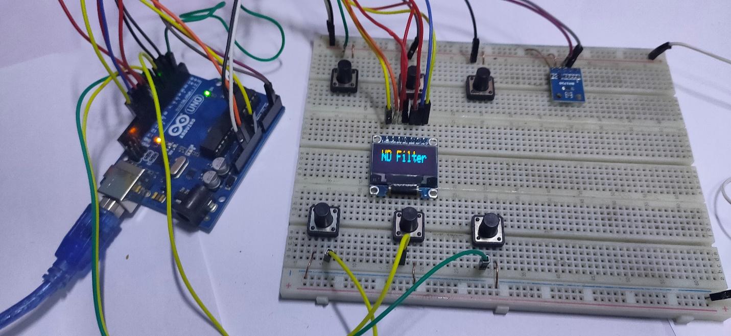
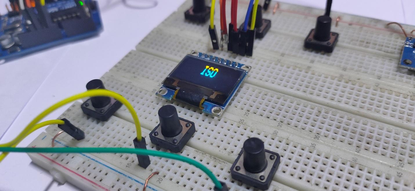
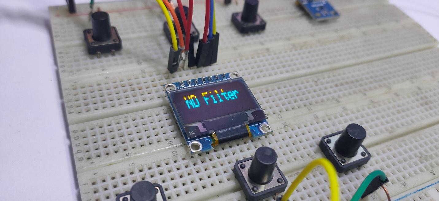
Once you have all of the hardware properly connected, your project should look something like the build in the following image.
The project once all of the hardware is connected.
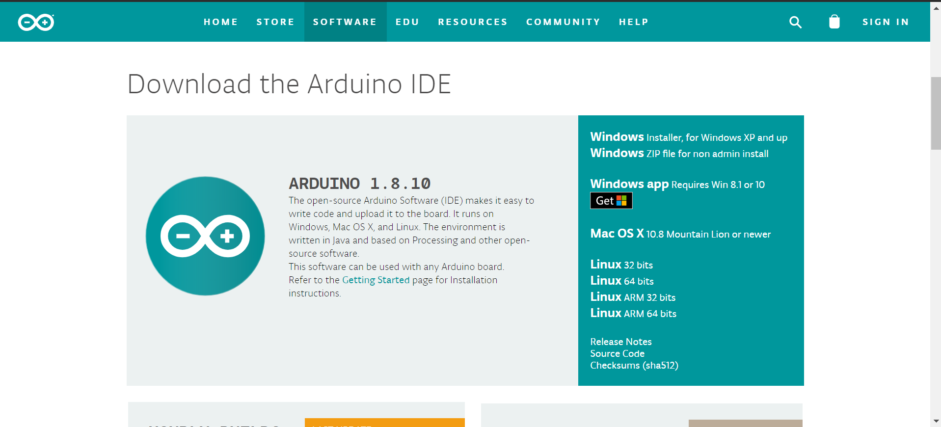
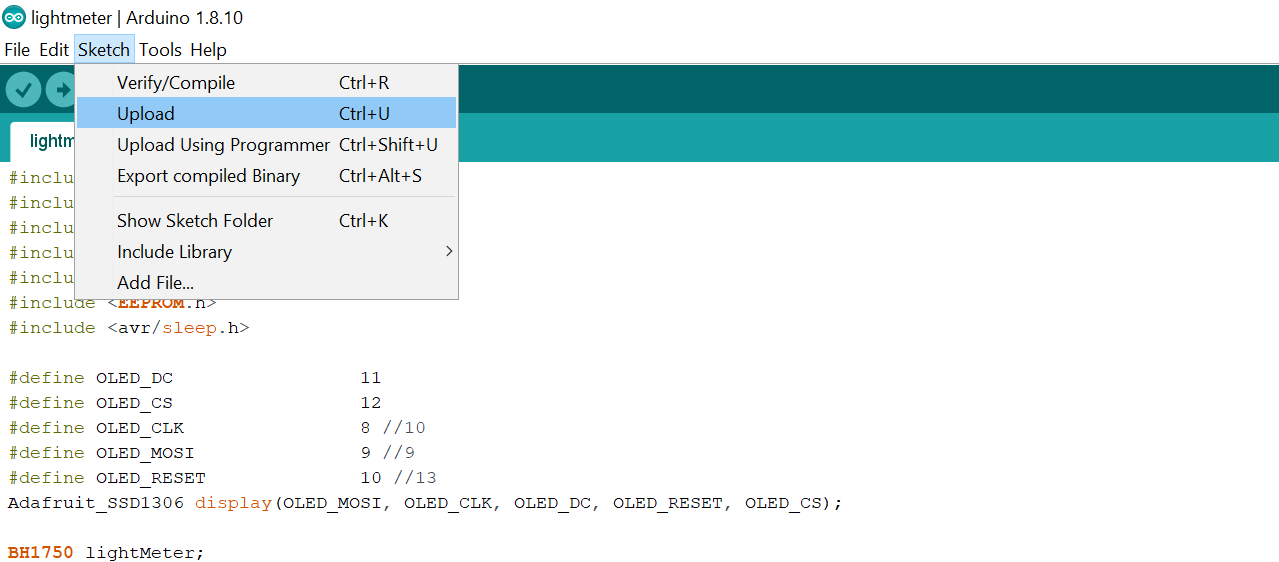
Download the Arduino IDE and all the necessary libraries from the links above. If you are a beginner, then please follow How to Get Started With Arduino IDE to help you set up the Arduino IDE on your computer.
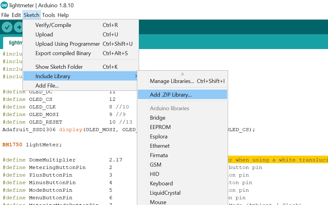
To add the downloaded libraries to Arduino go to Sketch —> Include Library —> Add. Zip Library. Repeat this step for all libraries.
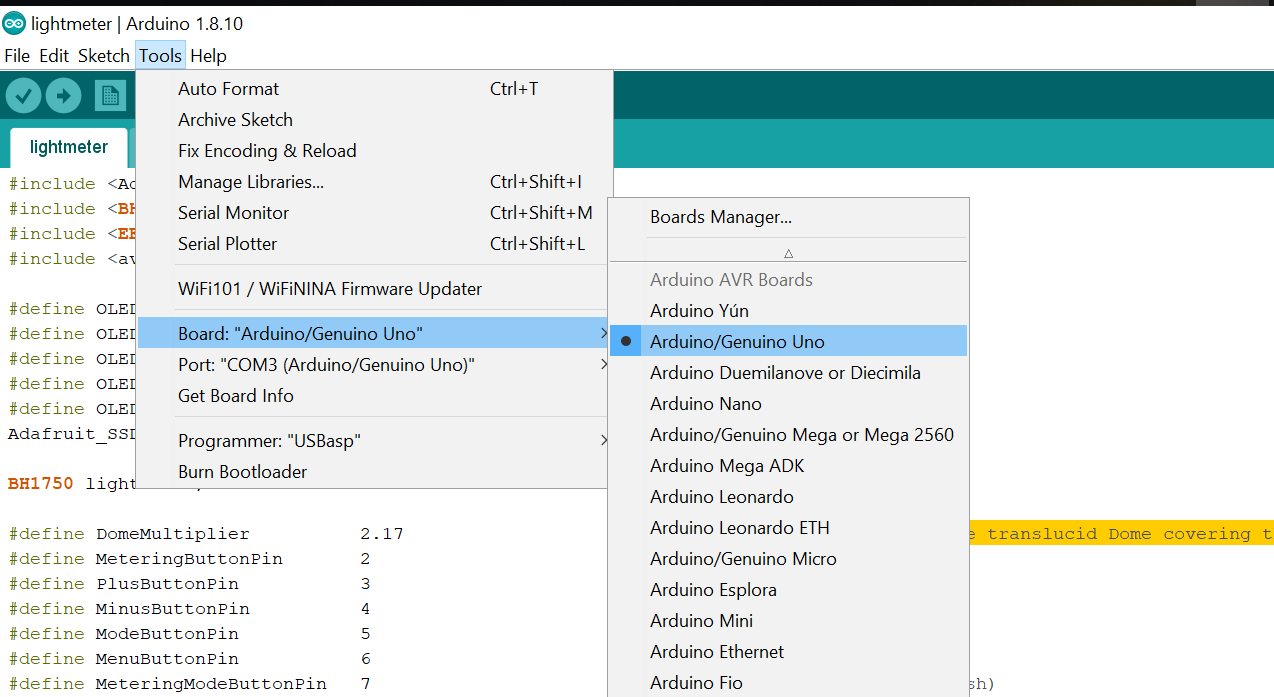
After adding the libraries, connect your Arduino board with your computer. Then go to Tools —> Board —> Select Arduino UNO board.
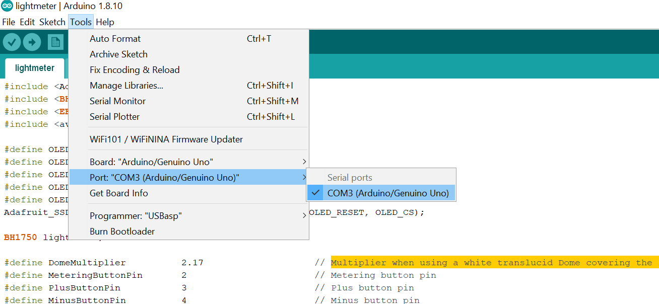
Now go to Tools —> Port —> Select COM PORT. In my case, it’s COM3.
After uploading the code, power up your Arduino. You should see the OLED displaying info. There are six buttons in the user interface that do the following:
- Button 1 - Metering
- Button 2 - + the value
- Button 3 - - the value
- Button 4 - Metering Mode
- Button 5 - Menu
- Button 6 - Priority (ISO/ No filter)
