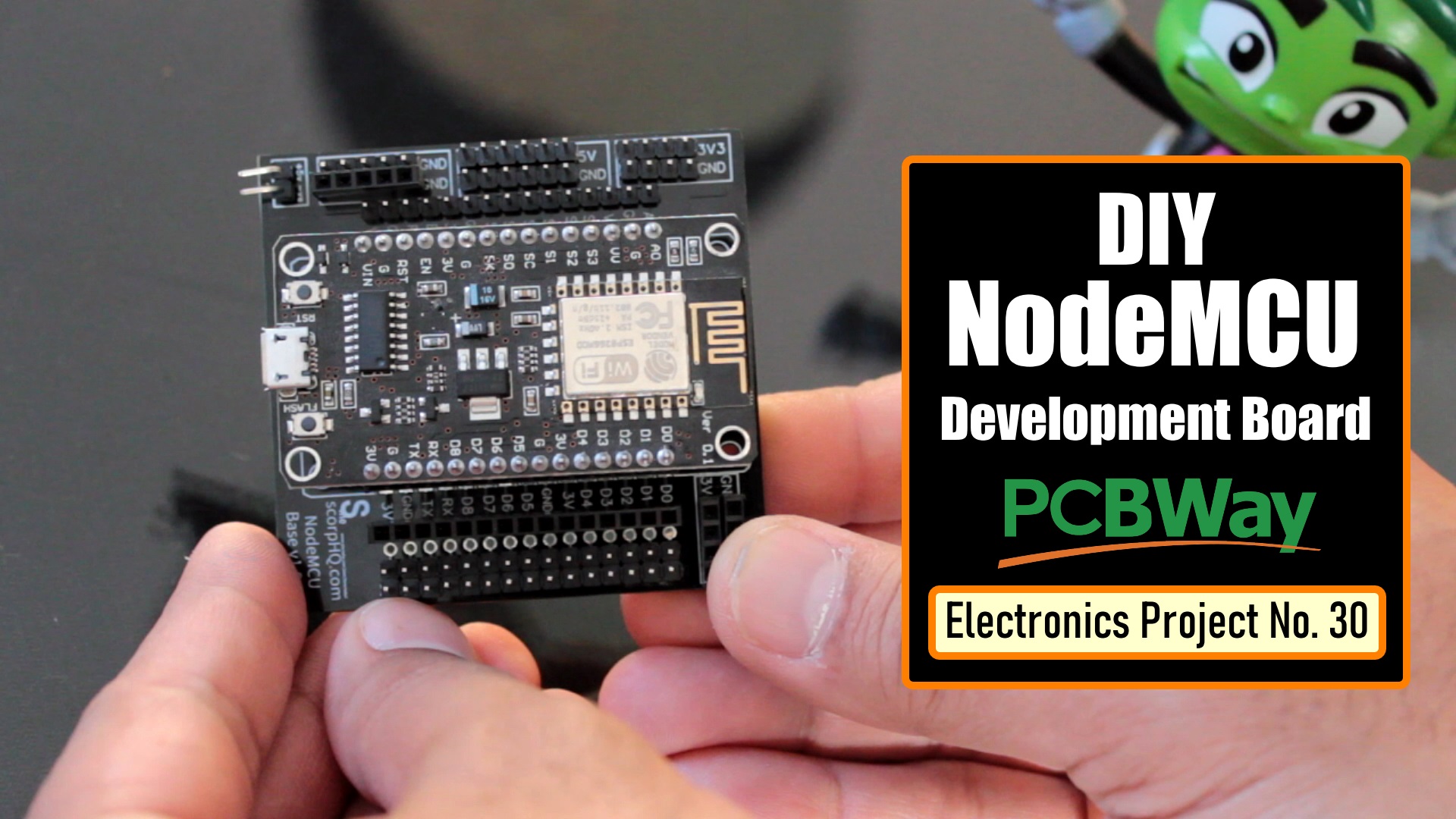
I designed a replica of the NodeMCU Development Board, which, 10 of them I got fabricated for just $5.
If you have ever programmed a NodeMCU, then I bet you know the pain you have to go through while connecting sensors to NodeMCU on a breadboard.
I looked for various solution on the web and found "NodeMCU Development Boards" for around $6 to $7. Well, I wasn't ready to spend that much for a simple projects. So, I went ahead and designed a replica of those boards, which, 10 of them I got fabricated from PCBWay for just $5.
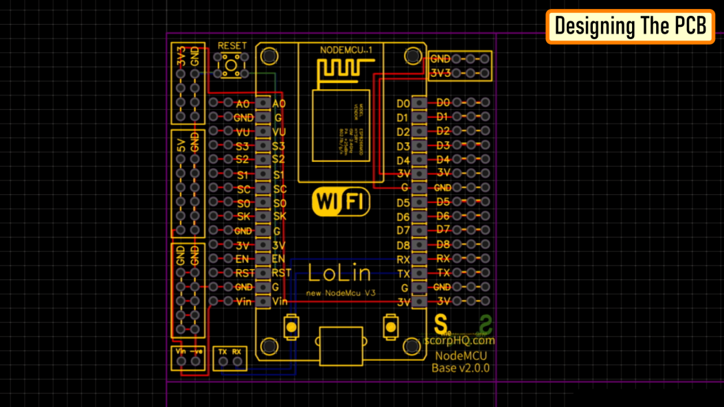
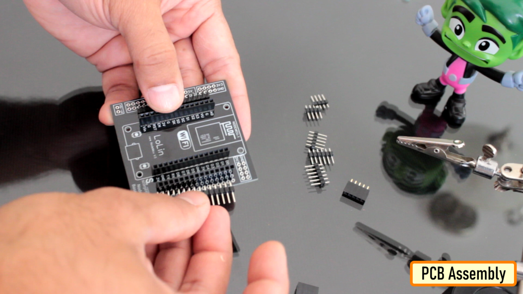
Let me first show you the design of the board.
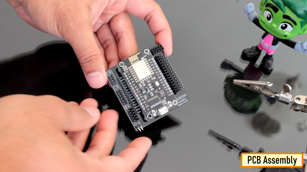
I have placed the NodeMCU in the middle of the board.
On the right hand side are the extensions of all the digital pins. And on the left hand side are the extensions of the left hand side pins.
Starting from left to right I have the VIN and the -VE pin to power up the NodeMCU at the bottom left hand side of the board. NodeMCU has an inbuilt LDO voltage regulator which keep the voltage level at 3.3v so there is no need for an additional voltage regulator. Just above that, is a series of GND pins. On top of that is a series of +5v and GND pins, followed by a series of 3.3v and GND pins. I have also added a series of 3v3 and GND pins on the top right hand side of the board.
Then there is a reset button and a set of TX and RX pins for serial communication.
On the same breakout board I have also added an Arduino Nano's Development Board.
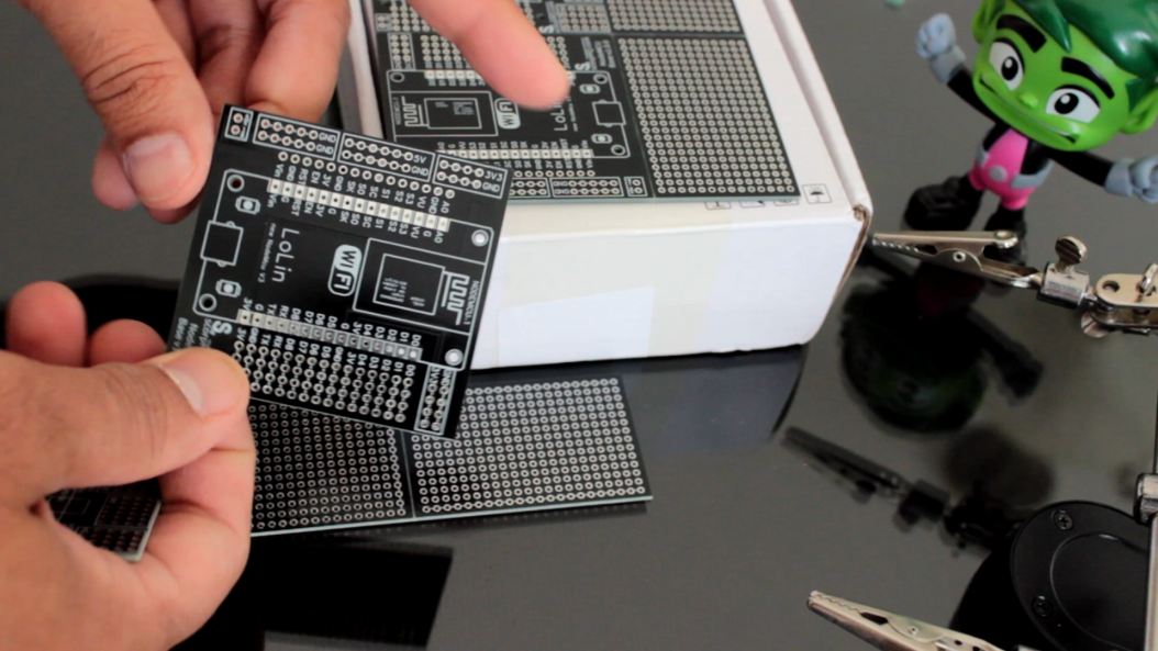
Since, I had a fair bit of real-estate left on my board, I created a generic PCB out of the left over space.
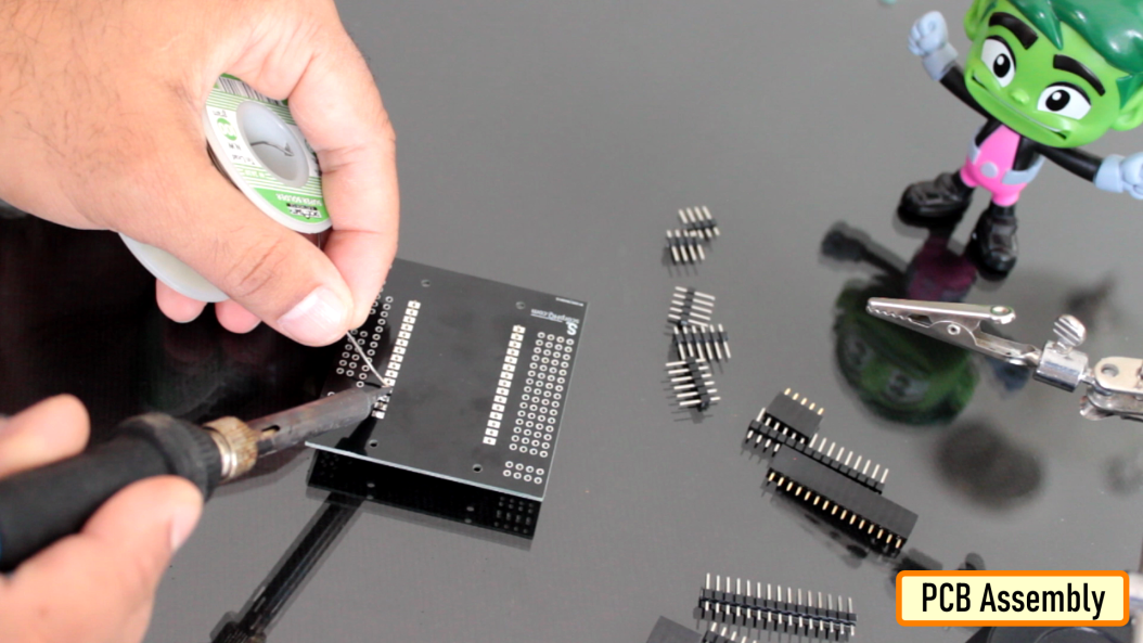
Lets start by soldering the male and the female pin headers to the board. It really doesn't matter, what order you solder the components to the board. The only think to remember is that, do not solder a component that blocks another one.
As you can see, I am soldering both male and female pin headers side by side on the board so that sensors with either male or female pin header can be hooked up to the board, making it more generic and expandable.
So, this is how the final setup looks like. Please comment and let me know if there is any scope of improvement, thanks.
Thanks
Thanks again for checking my post. I hope it helps you.
If you want to support me subscribe to my YouTube Channel: https://www.youtube.com/user/tarantula3
Blog Posts: https://diyfactory007.blogspot.com/2021/11/nodemcu-development-board.html
YouTube: https://youtu.be/y2m2nh7wHaY
Odysee : https://odysee.com/@Arduino:7/DIY---NodeMCU-Development-Board:1
cos.tv : https://cos.tv/videos/play/32048547001832448
Schema : https://drive.google.com/file/d/1XRR2sNZ5t4NhLFla9X3DyjaPAujrjeGY/view?usp=sharing
Support My Work:
BTC: 1M1PdxVxSTPLoMK91XnvEPksVuAa4J4dDp
LTC: MQFkVkWimYngMwp5SMuSbMP4ADStjysstm
DOGE: DDe7Fws24zf7acZevoT8uERnmisiHwR5st
ETH: 0x939aa4e13ecb4b46663c8017986abc0d204cde60
BAT: 0x939aa4e13ecb4b46663c8017986abc0d204cde60
LBC: bZ8ANEJFsd2MNFfpoxBhtFNPboh7PmD7M2
Thanks, ca again in my next tutorial.