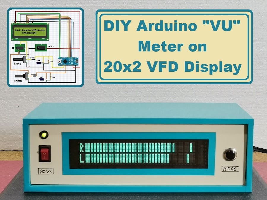
How to make a VU meter with 38 bars per channel on a modified 20x2 VFD display.
A vacuum fluorescent display (VFD) is a display device commonly used on consumer electronics equipment. VFD emits a very bright light with high contrast. Due to these features and the beautiful retro look, the devices made with these displays are very popular with do it yourself enthusiasts, but at the same time very complex in terms of connection and the way of communication with the microcontroller.
Another difficulty is the fact that in most cases they have almost no documentation and there are no libraries to simplify the code.
This time I will show you how to make a VU meter with 38 bars per channel on a 20x2 VFD display. It is very important to mention that in this project is used a VFD display of the type: "VFM202MDA", which contains PT6314 driver chip. This display with very little modification can be connected to the Arduino in the same way as the 16x2 Character LCD Display with the Hitachi HD44780 driver, which means that it uses the same libraries. Thus, with a very small change in the code that refers only to the number of displayed characters, almost any device based on the mentioned LCD display can be made on VFD.
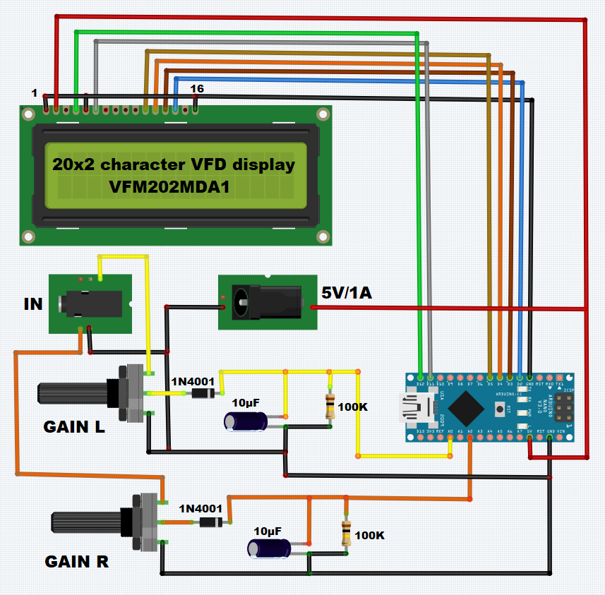
The presented device is very simple to build, and consists of several components:
- Arduino nano microcontroller
- VFM202MDA1 type VFD Display (slightly modified)
- and several resistors and capacitors
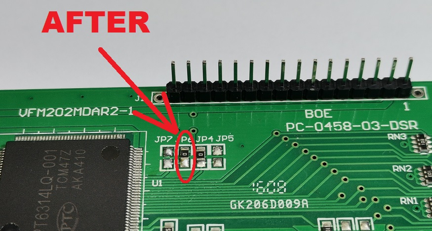
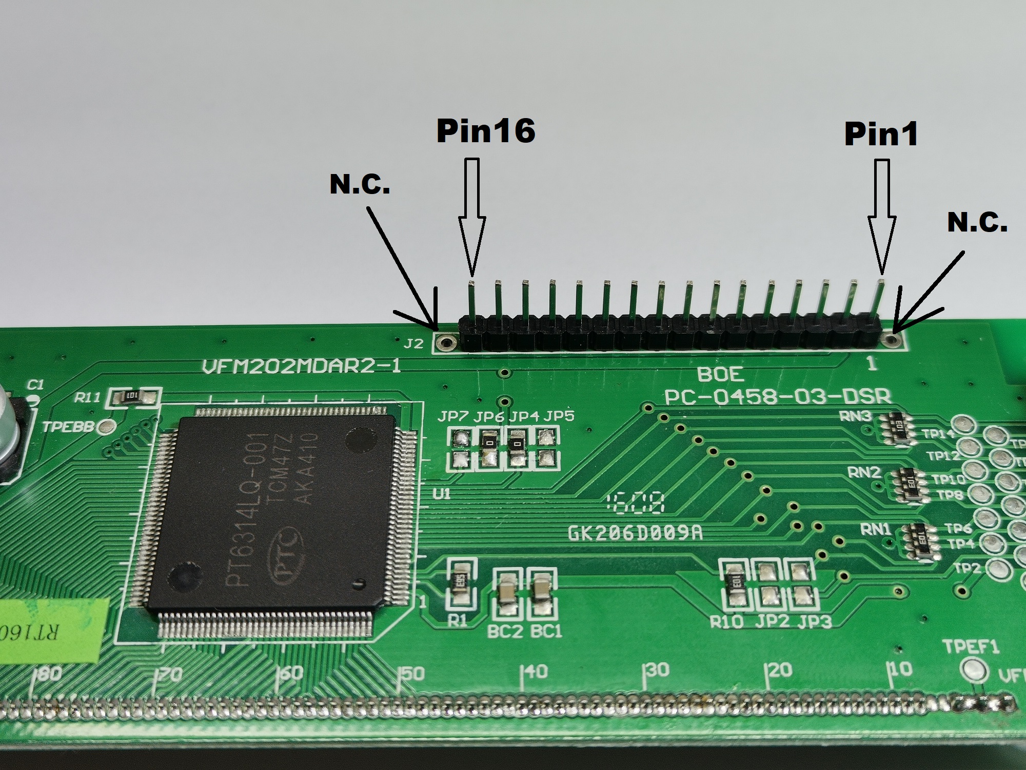
The modification of the VFD display consists in moving the short circuit from JP-7 to the JP-6 position. The picture below shows these places with a red circle, and also the communication pins that are compatible with the 16x2 LCD display.
The input consists of a stereo potentiometer to regulate the signal intensity. Next is the envelope follower with a filter. By changing the capacitance of the capacitor, the reaction speed of the VU meter also changes, specifically the return of each bar to its original position.
Finally, the device is built into a suitable housing made of PVC material with a thickness of 3 and 5 mm and coated with self-adhesive colored wallpaper.
#include <LiquidCrystal.h>
LiquidCrystal lcd(12, 11, 5, 4, 3, 2);// RS,E,D4,D5,D6,D7
byte a1[8]={
  0b00000,0b11011,0b11011,0b11011,0b11011,0b11011,0b11011,0b11011};
byte a2[8]={
  0b00000,0b11000,0b11000,0b11000,0b11000,0b11000,0b11000,0b11000};
byte a3[8]={
  0b00000,0b00011,0b00011,0b00011,0b00011,0b00011,0b00011,0b00011};
byte znak_r[8]={ // R
  B00000,
  B11100,
  B10010,
  B10010,
  B11100,
  B11000,
  B10100,
  B10010};
byte znak_l[8]={ // L
  B00000,
  B10000,
  B10000,
  B10000,
  B10000,
  B10000,
  B10000,
  B11110};
int u_r,u_l,i=1,x,u_maxr,u_maxl,z,z1,u_r0[19],u_l0[19];
unsigned long time1;
long decayTime = 0;
void setup(){
  analogReference(INTERNAL);
  lcd.begin(16, 2);// LCD 16X2
  lcd.createChar(0,a1);
  lcd.createChar(1,a2);
  lcd.createChar(2,znak_r);
  lcd.createChar(3,znak_l);
  lcd.createChar(4,a3);
  pinMode(A0,INPUT);
  pinMode(A2,INPUT);
    String main_version = "1.2";
    String mircemk = "* mircemk *";

  for (int i = 0; i <= 20; i++)
  {
    lcd.setCursor(4, 0);
    lcd.print(mircemk.substring(0, i));
    delay(100);
  }

  mircemk = "    VU meter " + main_version;

  for (int i = 0; i <= mircemk.length(); i++)
  {
    lcd.setCursor(0, 1);
    lcd.print(mircemk.substring(0, i));
    delay(100);
  }

  delay(500);

  lcd.clear();
  lcd.setCursor(5, 0);
  lcd.print("Loading...");

  for (int i = 0; i < 20; i++)
  {
    lcd.setCursor(i, 1);
    lcd.write(1);

    delay(100);
  }

  delay(5);
  lcd.clear();

  decayTime = millis();
}


void loop(){
  lcd.setCursor(0,0);// R
  lcd.write((uint8_t)2);
  lcd.setCursor(0,1);
  lcd.write((uint8_t)3);// L

  u_r = analogRead(A0); // измерение R
  u_l = analogRead(A2); // измерение L

  for(int z=1,z1=0,z2=30;z<=19;z++,z1=z1+30,z2=z2+30){ // l+r
    if(u_l>z1){
      lcd.setCursor(z,1);
      lcd.write((uint8_t)1);
    }
    if(u_r>z1){
      lcd.setCursor(z,0);
      lcd.write((uint8_t)1);
    }
    if(u_l>z2){
      lcd.setCursor(z,1);
      lcd.write((uint8_t)0);
    }
    if(u_r>z2){
      lcd.setCursor(z,0);
      lcd.write((uint8_t)0);
    }
  }

  i++;
  if(i<=19){
    u_l0[i]=u_l;
    u_r0[i]=u_r;
  }
  else{
    i=1;
  }
  if(i==19){
    u_maxr=0;
    u_maxl=0;
    for(x=1;x<=19;x++){
      u_maxl=max(u_maxl,u_l0[x]);
      u_maxr=max(u_maxr,u_r0[x]);
    }
  }

  if(u_maxl<=u_l){
    u_maxl=u_l;
  }
  if(u_maxr<=u_r){
    u_maxr=u_r;
  }

  for(z=1,z1=0;z<=19;z++,z1=z1+30){
    if(u_maxl > z1 && u_maxl <= z1+19){
      lcd.setCursor(z,1);
      lcd.write((uint8_t)1);
    }
    if(u_maxl > z1+19 && u_maxl <= z1+30){
      lcd.setCursor(z,1);
      lcd.write((uint8_t)4);
    }

    if(u_maxr > z1 && u_maxr <= z1+19){
      lcd.setCursor(z,0);
      lcd.write((uint8_t)1);
    }
    if(u_maxr > z1+19 && u_maxr <= z1+30){
      lcd.setCursor(z,0);
      lcd.write((uint8_t)4);
    }
  }
  delay(30);
  lcd.clear();
}