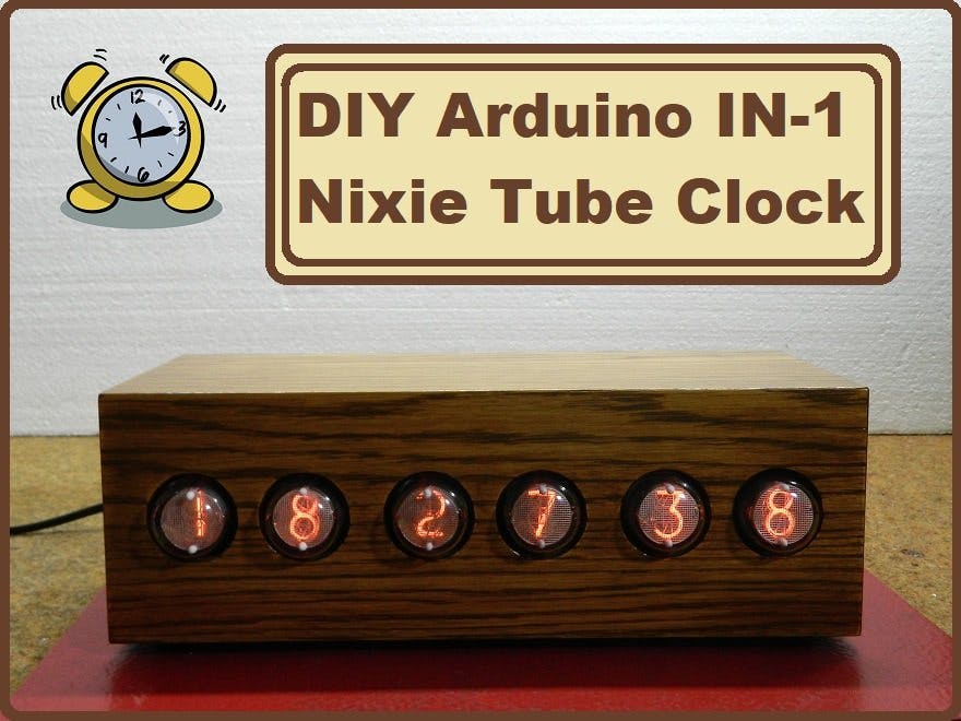
This is another one of the many unusual clocks you can see in some of my previous projects. IN-1 nixie tubes are relatively cheap.
Nixie tube is an electronic device used for displaying numerals or other information using glow discharge. The glass tube contains a wire-mesh anode and multiple cathodes, shaped like numerals or other symbols. Applying power to one cathode surrounds it with an orange glow discharge.
This time I will show you how to make a nice retro look clock with the help of 6 such tubes. This is another one of the many unusual clocks you can see in some of my previous videos. I decided to make this device with IN-1 nixie tubes for reasons that can easily be find on eBay, and are relatively inexpensive - 6 pieces cost around $ 30 total.
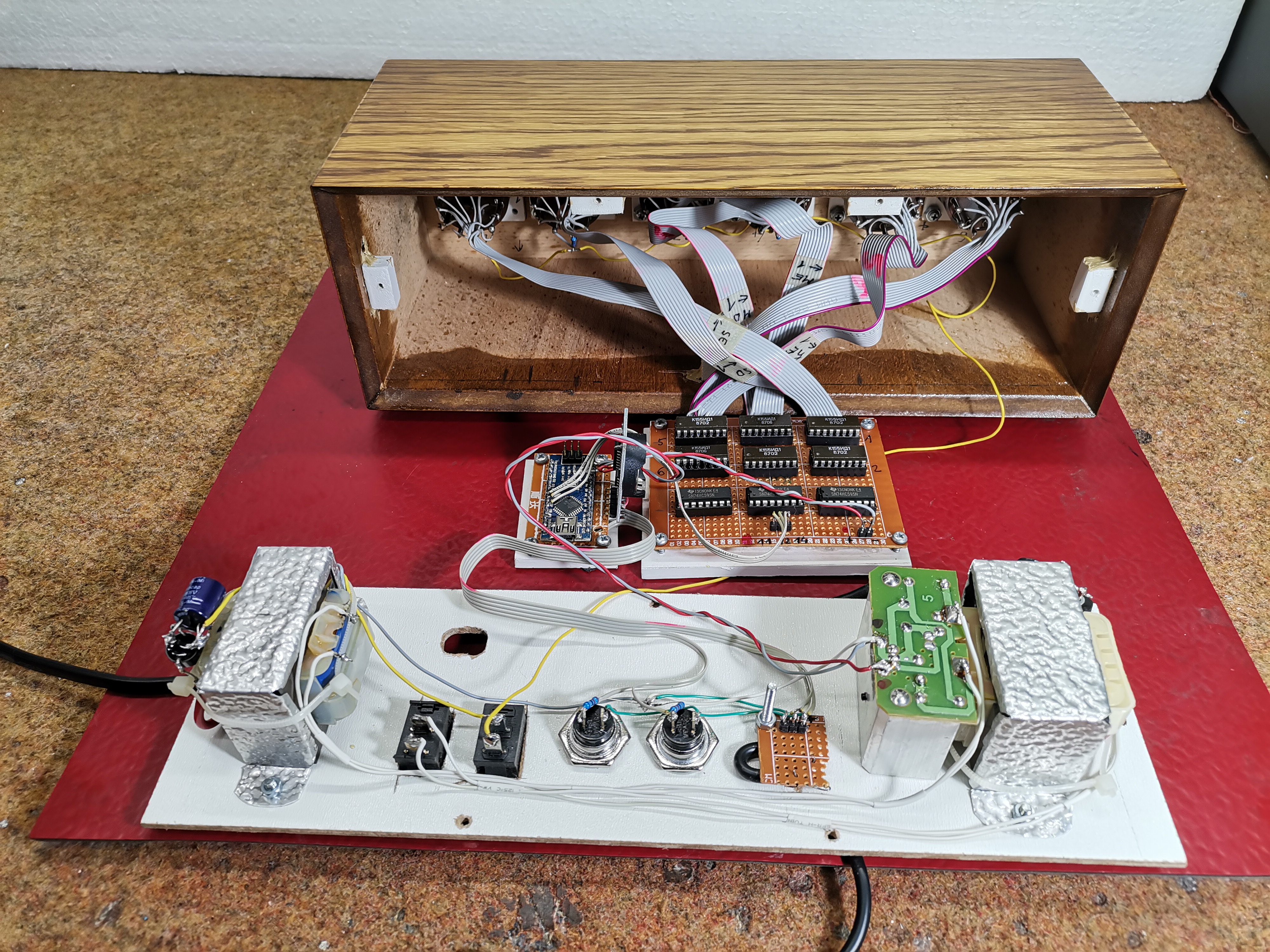
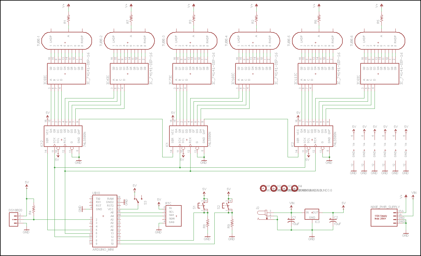
The device is relatively simple to build due to the use of the Arduino microcontroller, given that such clocks are dominated by discrete electronic elements and are complex for self-construction. It consists of the following components:
- Six IC drivers for nixie tubes type: K155 or SN74141
- Three SN74HC595 shift registers
- Arduino Nano microcontroller
- DS3231 realtame clock module
- DS18B20 temperature sensor
- And at the end the Powerrr supply
The power supply unit is performed in a slightly unusual way to get 5 volts for the Arduino and 200V anode voltage. We have two identical transformers 220V to 6V. We connect the secondary from the first to the secondary winding on the second transformer. So now at the primary output winding on the second transformer we get 180-200 Volts, taking into account the losses that occur in the transformation. We use this voltage as the anode voltage for the tubes. From the place where the two secondary windings are interconnected, we take a voltage of 6 volts which we then carry to the Arduino through a rectifier with a stabilizer.
As it is known, the lifespan of these tubes is relatively short, especially if a single digit is activated for a long time. For this reason the code is made so that every minute all digits scroll from 0 to 9, and it lasts a few seconds. Also at a certain time interval is displayed the temperature obtained from the ds18B20 temperature sensor which is located outside the housing due to temperature independence.
As we can see, we have two buttons on the back of the watch. One scrolls all the digits, and the other button is used to display the current temperature. Finally, the clock is placed in a convenient wooden box that is well processed and varnished, so the watch got a complete retro look.
// Nixie-Bot
// Created 2013
// Scott-Bot.com

#include <Wire.h>
#include "RTClib.h"
#include <OneWire.h>

const int button1Pin = 11;
const int button2Pin = 10;

int DS18S20_Pin = 2; //DS18S20 Signal pin on digital 2

//Temperature chip i/o
OneWire ds(DS18S20_Pin); // on digital pin 2
int TempReading;
int TempDigit1;
int TempDigit2;
RTC_DS1307 RTC;
DateTime now;

//Pin connected to ST_CP of 74HC595
int latchPin = 6;
//Pin connected to SH_CP of 74HC595
int clockPin = 7;
////Pin connected to DS of 74HC595
int dataPin = 5;

int testpattern = 0;

int button1State = 0;
int button2State = 0;

unsigned long SecondCount = 0; // Second counter
unsigned long MinuteCount = 0; // Second counter
int randint;

byte DataOut1 = B11111111;
byte DataOut2 = B11111111;
byte DataOut3 = B11111111;

void setup () {
  pinMode(button1Pin, INPUT);
  pinMode(button2Pin, INPUT);
  pinMode(latchPin, OUTPUT);
  pinMode(clockPin, OUTPUT);
  pinMode(dataPin, OUTPUT);
  Serial.begin(57600);
  Wire.begin();
  RTC.begin();


  if (! RTC.isrunning()) {
    Serial.println("RTC is NOT running!");
    // following line sets the RTC to the date & time this sketch was compiled
    RTC.adjust(DateTime(__DATE__, __TIME__));
  }

  //Wait for power supply to power up
  delay(1000);
  getTemp();

}

void loop () {

  // Every minute display a test pattern
  if (millis()-MinuteCount > 60000) {
    MinuteCount = millis();
    if (testpattern == 0) {
      DispTemp();
      testpattern = 1;
    } else if (testpattern == 1) {
      ScrollPattern();
      testpattern = 0;
    }
  } else if (millis()-SecondCount > 1000) {
    SecondCount = millis();
    GetTime();
    DispTime();
  }

  button1State = digitalRead(button1Pin);
  button2State = digitalRead(button2Pin);
  if (button1State == HIGH) {
    // Display the temperature pattern
    DispTemp();
    MinuteCount = millis();
  }
  if (button2State == HIGH) {
    // Display the scrolling pattern
    ScrollPattern();
    MinuteCount = millis();
  }

}

// Scroll the temperature across the display
void DispTemp() {

  for(int j=1; j<=3; j++) {
    TempReading = getTemp();
    TempDigit1 = TempReading/10;
    TempDigit2 = TempReading%10;
    SetDigit(1, 10);
    SetDigit(2, 10);
    SetDigit(3, 10);
    SetDigit(4, 10);
    SetDigit(5, 10);
    SetDigit(6, 10);
    for (int i = -1; i<=7; i++) {
      SetDigit(i-1, 10);
      SetDigit(i, TempDigit1);
      SetDigit(i+1, TempDigit2);
      shiftOut();
      delay(333);
    }
  }
}

// Displays the time
void DispTime() {
  int hourdigit1 =(now.hour())/10;
  int hourdigit2 =(now.hour())%10;
  int mindigit1 =(now.minute())/10;
  int mindigit2 =(now.minute())%10;
  int secdigit1 =(now.second())/10;
  int secdigit2 =(now.second())%10;
  SetDigit(1, hourdigit1);
  SetDigit(2, hourdigit2);
  SetDigit(3, mindigit1);
  SetDigit(4, mindigit2);
  SetDigit(5, secdigit1);
  SetDigit(6, secdigit2);
  shiftOut();
}

void ScrollPattern() {
  // Blank the digits
  SetDigit(1, 10);
  SetDigit(2, 10);
  SetDigit(3, 10);
  SetDigit(4, 10);
  SetDigit(5, 10);
  SetDigit(6, 10);
  delay(250);
  //Scroll Loop
  for (int i = 1; i<=6; i++) {
    SetDigit(1, i);
    SetDigit(2, i-1);
    SetDigit(3, i-2);
    SetDigit(4, i-3);
    SetDigit(5, i-4);
    SetDigit(6, i-5);
    shiftOut();
    delay(200);
  }
  for (int i = 7; i<=39; i++) {
    SetDigit(1, (i)%10);
    SetDigit(2, (i-1)%10);
    SetDigit(3, (i-2)%10);
    SetDigit(4, (i-3)%10);
    SetDigit(5, (i-4)%10);
    SetDigit(6, (i-5)%10);
    shiftOut();
    delay(200);
  }
  for (int i = 10; i<=16; i++) {
    SetDigit(1, i);
    SetDigit(2, i-1);
    SetDigit(3, i-2);
    SetDigit(4, i-3);
    SetDigit(5, i-4);
    SetDigit(6, i-5);
    shiftOut();
    delay(200);
  }
}

// Sets a digit of the display
void SetDigit(int Digit, int Number) {

  byte BinNum;

  if ( Number == 0) {
    BinNum= B0000;
  }
  else if ( Number == 1) {
    BinNum= B1001;
  }
  else if ( Number == 2) {
    BinNum= B1000;
  }
  else if ( Number == 3) {
    BinNum= B0111;
  }
  else if ( Number == 4) {
    BinNum= B0110;
  }
  else if ( Number == 5) {
    BinNum= B0101;
  }
  else if ( Number == 6) {
    BinNum= B0100;
  }
  else if ( Number == 7) {
    BinNum= B0011;
  }
  else if ( Number == 8) {
    BinNum= B0010;
  }
  else if ( Number == 9) {
    BinNum= B0001;
  }
  else {
    BinNum= B1010;
  }

  if ( Digit == 1) {
    DataOut1 &= B00001111;
    DataOut1 |= (BinNum << 4);
  }
  else if ( Digit == 2) {
    DataOut1 &= B11110000;
    DataOut1 |= BinNum;
  }
  else if ( Digit == 3) {
    DataOut2 &= B00001111;
    DataOut2 |= (BinNum << 4);
  }
  else if ( Digit == 4) {
    DataOut2 &= B11110000;
    DataOut2 |= BinNum;
  }
  else if ( Digit == 5) {
    DataOut3 &= B00001111;
    DataOut3 |= (BinNum << 4);
  }
  else if ( Digit == 6) {
    DataOut3 &= B11110000;
    DataOut3 |= BinNum;
  }

}

// Shifts out the data to the shift registers
void shiftOut() {
  // This shifts 8 bits out MSB first,
  //on the rising edge of the clock,
  //clock idles low

  //internal function setup
  int i=0;
  int pinState;

  //clear everything out just in case to
  //prepare shift register for bit shifting
  //ground latchPin and hold low for as long as you are transmitting
  digitalWrite(latchPin, 0);
  digitalWrite(dataPin, 0);
  digitalWrite(clockPin, 0);

  //for each bit in the byte myDataOutďż˝
  //NOTICE THAT WE ARE COUNTING DOWN in our for loop
  //This means that %00000001 or "1" will go through such
  //that it will be pin Q0 that lights.
  for (i=7; i>=0; i--)  {
    digitalWrite(clockPin, 0);

    //if the value passed to myDataOut and a bitmask result
    // true then... so if we are at i=6 and our value is
    // %11010100 it would the code compares it to %01000000
    // and proceeds to set pinState to 1.
    if ( DataOut1 & (1<<i) ) {
      pinState= 1;
    }
    else {
      pinState= 0;
    }

    //Sets the pin to HIGH or LOW depending on pinState
    digitalWrite(dataPin, pinState);
    //register shifts bits on upstroke of clock pin
    digitalWrite(clockPin, 1);
    //zero the data pin after shift to prevent bleed through
    digitalWrite(dataPin, 0);
  }

  //stop shifting
  digitalWrite(clockPin, 0);

  // Shift the second word
  for (i=7; i>=0; i--)  {
    digitalWrite(clockPin, 0);

    if ( DataOut2 & (1<<i) ) {
      pinState= 1;
    }
    else {
      pinState= 0;
    }

    digitalWrite(dataPin, pinState);
    digitalWrite(clockPin, 1);
    digitalWrite(dataPin, 0);
  }

  digitalWrite(clockPin, 0);

  // Shift the third word
  for (i=7; i>=0; i--)  {
    digitalWrite(clockPin, 0);

    if ( DataOut3 & (1<<i) ) {
      pinState= 1;
    }
    else {
      pinState= 0;
    }

    digitalWrite(dataPin, pinState);
    digitalWrite(clockPin, 1);
    digitalWrite(dataPin, 0);
  }

  digitalWrite(clockPin, 0);

  digitalWrite(latchPin, 1);
}

// Read from the real time clock
void GetTime () {
  now = RTC.now();
}

float getTemp(){
 //returns the temperature from one DS18S20 in DEG Celsius

 byte data[12];
 byte addr[8];

 if ( !ds.search(addr)) {
   //no more sensors on chain, reset search
   ds.reset_search();
   return -1000;
 }

 if ( OneWire::crc8( addr, 7) != addr[7]) {
   Serial.println("CRC is not valid!");
   return -1000;
 }

 if ( addr[0] != 0x10 && addr[0] != 0x28) {
   Serial.print("Device is not recognized");
   return -1000;
 }

 ds.reset();
 ds.select(addr);
 ds.write(0x44,1); // start conversion, with parasite power on at the end

 byte present = ds.reset();
 ds.select(addr);
 ds.write(0xBE); // Read Scratchpad


 for (int i = 0; i < 9; i++) { // we need 9 bytes
  data[i] = ds.read();
 }

 ds.reset_search();

 byte MSB = data[1];
 byte LSB = data[0];

 float tempRead = ((MSB << 8) | LSB); //using two's compliment
 float TemperatureSum = tempRead / 16;
 TemperatureSum = (TemperatureSum * 9.0)/ 5.0 + 32.0;
 return TemperatureSum;

}


