Clean your yard from your smartphone or preset a job for AYSE to follow!
The Situation
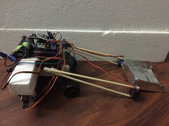
Going outside to do chores like cleaning up after and feeding my dogs, raking leaves, and getting rid of fireant mounds that attack my smaller dogs is not only inconvenient and annoying in the hot Texas summer, but dangerous as well. Working outside for extended periods of time can cause sunburns and even heat strokes. I don't expect my 100 degree weather to get any better soon, so I came up with AYSE. Short for Autonomous Yard Scooping Entity, the robot features:
- Arduino Uno with Motor Shield and Particle Photon
- Strong Reused Aluminum Scoop
- Magnetic Odometer Sensor Setup (built with Infineon 3D 2Go Magnetic Sensor)
- Single Command setting in the works
- Scalability for different robot sizes
With robotics and autonomy increasingly being introduced to the consumer, this is an ideal solution to a problem many people experience.
Hardware
A double gearbox allows for independent rear wheel control. The aluminum scoop is build completely out of recycled resources. The arm and scoop use four servos for careful object manipulation. The Magnetic Odometer Sensor Setup allows for distance traveled to be recorded and ultimately allows setting of commands. Instructions on making MOSS will be on my profile, as that's another project on it's own.
Software
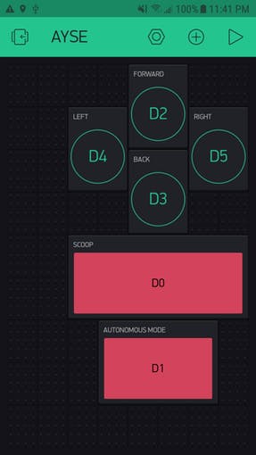
Although the current library of commands is small, expansion is in the works. Current methods include preset positions for the arm and scoop, turning and moving in four directions, and support for a repetitive task in Autonomous Mode. AYSE also currently uses Blynk as I wanted to try something new, but I will look at different user interfaces for the future (controlling more than one AYSE at a time?).
https://github.com/mitomon/AYSE-Library
Control
AYSE takes advantage of current home security systems by allowing the user to control it in real time. The user can tune into their camera system to watch AYSE and move it around with the app. If a task is too repetitive, a simple button combination if pressed and the robot starts recording the distance traveled. Once autonomous mode is enabled, the rover will then carry out the same task until commanded to stop.
Building
The base is made out of an old phone PCB that I scraped clean of components and covered in electrical tape. I hot glued a hard foam block cut into shape using a hot wire foam cutter. If you want to build one, check out this link. The block has an overhanging "arm" to hold the MOSS in place. The Styrofoam block was cut to fit the phone PCB and is 1 inch thick. Under the PCB, I assembled the double gearbox in a 38.2:1 gear ratio (the box comes with instructions, don't worry). You can use a different double gear box or configuration if you want, just make sure it is a Double gearbox so that the motors can be controlled independently of each other. Now just add wheels and you're good to go!
As long as you have a double gearbox and something to hold your boards in place, the specifics of the chassis are not that important.
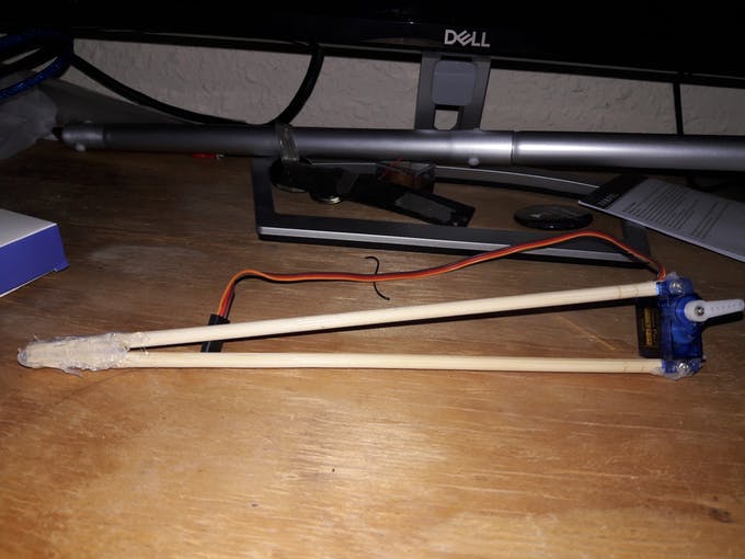
For each arm, grab a couple of chopsticks and two servos. I used 9 gram servos for the scoop servos and larger ones for the arms themselves. Glue two chopsticks into a V so that your smaller servos can fit inside snugly. Screw the servos into place and add some hot glue for good measure. Remember to flip the servo orientation for each arm as they will be facing opposite directions. We'll also have to deal with this in the code later.
Once you have both arms, attach the ends to the larger servos at the tip of the V with hot glue. Attach the larger servos, now the arm base, onto the center of your chassis with hot glue. Make sure they are facing opposite directions(to the outside from your chassis).
I've added more pictures for the scoop as it is a bit more complicated to build.
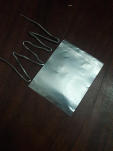
First, grab some thick aluminum wire to make a sort of skeleton for your scoop. This will make sure the aluminum sheets we use later do not bend. Make W shapes and leave an extra inch at the ends. The extra wire will give us a place to secure the back of our scoop.
For the aluminum sheets that cover the skeleton, grab a couple of soda cans and cut to top and bottom parts out. Cut the remaining cylinder once from top to bottom to create a rectangle. Fold this rectangle in half, leaving about 1/4" extra on one side. This way we can bend that piece in on itself to hold the aluminum plate in place. Push the skeleton into the gap in the plate fully and use aluminum tape to seal the end without the extra length of wire.
Now make another aluminum plate and push it into the assembly sideways with the gaps facing the left and right. Do not try to fit the skeleton into this,.The plate goes below the skeleton inside the other plate. Fold it up so that you have the same amount of extra plate as you do wire. Now fold another aluminum sheet so that two edges come up to cover the sides like in a commercial backhoe loader. You can make notches to secure it inside the gap of the back part of the scoop as well. Being careful to leave holes for the servo wings, tape this and the back part of the scoop onto your assembly. Do not forget to seal the scoop by taping the corners. Attach the scoop to both servo wings(screw these into the servos beforehand) by screwing them in and adding a bit of tape.
So you've got yourself a dapper arm with scoop on a wheeled chassis, but now we need the brain.
First off, attach your Motor Shield onto the Arduino Uno. Next, grab your Particle Photon and line up Digital Pins 0-5 with the Arduino's Analog Pins 0-5. You have to use the digital pins as the code takes into account PMW. This is to save us 6 jumper wires. Use jumper wires to attach the Photon's VIN and GND to the Uno's 3.3v pin and one of the GND pins, respectively. Screw the rotator knob onto the Infineon 3D 2Go Magnetic Sensor and hot glue the center of the knob onto the center of the wheel with the overhanging Styrofoam "arm" that we built in the chassis. Make a small notch in the "arm" to make secure the sensor board.
On the scoop servos, use a needle to push the data(yellow/white) and power(red) pins out of the connector case. Now push them back into the other's position(data where power was and vice versa). This must be done so that the whole connector pin can be plugged into the motor shield's orange servo pins. Solder some wires to your motors and connect the motor on the right to Channel B and the motor on the left to Channel A on the motor shield. Split your 7v Li-ion battery's red wire with a switch (so we can turn the power on and off) and connect the resulting wires to the VIN and GND beside the motor channels.
Connect the arm servos together; they will act as one big servo. If you have a fancy servo connector or extra jumper wires, use those. If not, just use staples like I did to connect the three ports so only 3 jumper wires are needed instead of 6. Connect power to the 5v pin on the shield, GND to GND, and data to pin 10.
For the MOSS, hook up the I2C wires from the Infineon sensor to the white TWI IN connector on the shield. Make sure you don't mix up SDA and SCL as they are in different positions. Now we've got everything done except the code. The sensor is not on the schematic because Fritzing did not have it.
There are three different parts to the code, the Photon, the MOSS, and the Arduino Uno itself.
First, sign up to Blynk. It's free and useful for prototyping apps. Copy and paste this into build.particle.io and flash it into your Photon. This will allow you to control the Photon with the Blynk app. Replace the asterisks with your own authorization code.
For the MOSS, paste this code into the Infineon sensor. I'll add a link to the GitHub repo for this once it's up. Change the wheel diameter to your wheel's diameter for accurate distance readings. This program records the amount of rotations made, what direction they were made in, and reports it to its master(the UNO) through I2C.
For the Arduino Uno, download ayseBase.ino from the GitHub repo and upload it to your Uno. I think it is commented well, but then again I did write it. All of the methods before the Arduino's setup{} method will be placed in a.h header file in the future so that the base code isn't too big. The setup method itself consists of setting pinMode for pins A0-5(if you remember, these are connected to the Photon) as INPUT and setting up the output pins for the motor shield. We also attach the three servos (remember the larger ones are put together so they count as one) and begin communications with Serial for debugging and Wire for our slave sensor. Loop takes care of everything else. If you want to modify the servo scoop method(setScoopPos), keep in mind that the servos actually move in supplementary pairs. This means that if one servo is at 80, the other one must go to 100 for them to be as the same height. This is remedied in setScoopPos by subtracting the given angle from 180 for the second servo.
Result
The Autonomous Yard Scooping Entity can be controlled through a mobile device through wifi. If your wifi signal is too weak, add an antenna to the Photon to increase AYSE's range. I currently consider this an "alpha" build as it is a bit small for the yardwork I had in mind. In the future I plan on getting some stronger motors and servos and also add radio control for extended range. I am currently working on using ultrasonic sensors for mapping and added autonomy, so sta tuned. The current software was made to be scalable, no matter the size of the physical robot. In the further future, AYSE could even be used by governments to clean up parks and further improve their communities. For now, I hope to use AYSE to give consumers a window into the rapidly advancing robotics and autonomy industries, improving their lives and inspiring them while eliminating mundane everyday tasks.