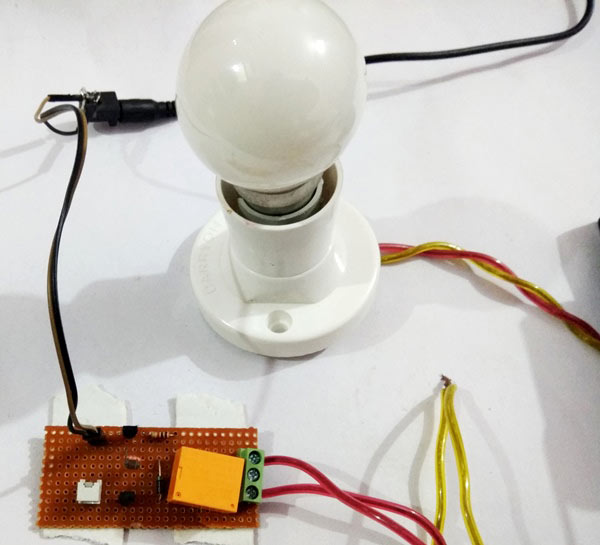
This automatic street light controller helps reduce the misuse of energy during daylight.
The main purpose of this project is to switch the street light from OFF to ON state and vice versa. This is done with the help of LIGHT DEPENDENT RESISTOR and a RELAY.
You may have seen the street light turning on and off automatically. It turns ON at night and turns OFF at day. With this observation, you can notice that there is some component used that detects the day and night and turns OFF and ON the light accordingly. This main function is done by the LDR (Light Dependent Resistor). Besides this component, there are other various components used as well.
This project is of utmost attention because, in smart cities, there is always a need for such automation. Moreover, sometimes the street lights remained ON during daylight and it drains a lot of energy. With the help of Automatic Street Light Controller, you can avoid such misuse of energy. There is no rocket science in this project as it simply consists of LDR, Relay, Resistors, Transistor and Power Supply.
Let’s move forward to learn much more about this project.
Components Required:
- Transistor BC547 -2
- LDR (Light Dependent Resistor)
- Relay
- Resistor 1k
- 100k Potentiometer
- Power Supply 12v -1
- Connecting wires
- Jumper wires
- Screw terminal Block 2 pin or 3 pin
- Bread Board or Perf Board
- 1n4007 Diode
- AC supply
- AC Load or Bulb
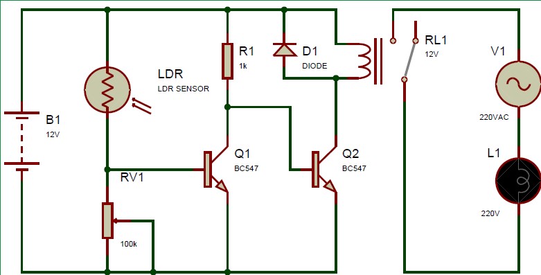
Circuit Diagram
In this circuit, the LDR (Light Dependent Resistor) is used. The resistance of LDR varies according to the light and darkness and with the help of this resistance, it detects whether it is a day or night. Its resistance increases at night and decreases at day. At the end of the circuit, a simple AC load (Bulb) is used and it is operated with the help of relay. To operate the relay, the two NPN transistors BC547 are used.
Operation
When the light falls on the LDR, the resistance of the LDR decreases and the transistor Q1 turns ON. But the collector is at a low state and the input signal to the second transistor Q2 is not enough to turn it ON. Hence, the relay remains OFF.
When there is darkness, LDR resistance increases, the signal becomes low at the base of Q1. The second transistor Q1 gets a high signal and turns ON the relay. The AC load is connected to a relay circuit hence the bulb turns ON as well.