Christmas tree with addressable Led Strip and arduino
Introduction: Arduino & WS2811 Christmas Tree
The tree decoration is made by my mother, I should tell her to share and make some Instructables.
Since there are other similar projects Christmas Lights Arduino and WS2811, Arduino Xmass tree I find them too complicated for newbies. So I decided to publish this simple and costless project, that you can try before facing more complicated ones, with even Bluetooth control and vu-meter.
Check the video
My family enjoyed designing the patterns, and I enjoyed coding them. I hope that you also enjoy it.
The tree decoration is made by my mother, I should tell her to share.
Bill of Materials
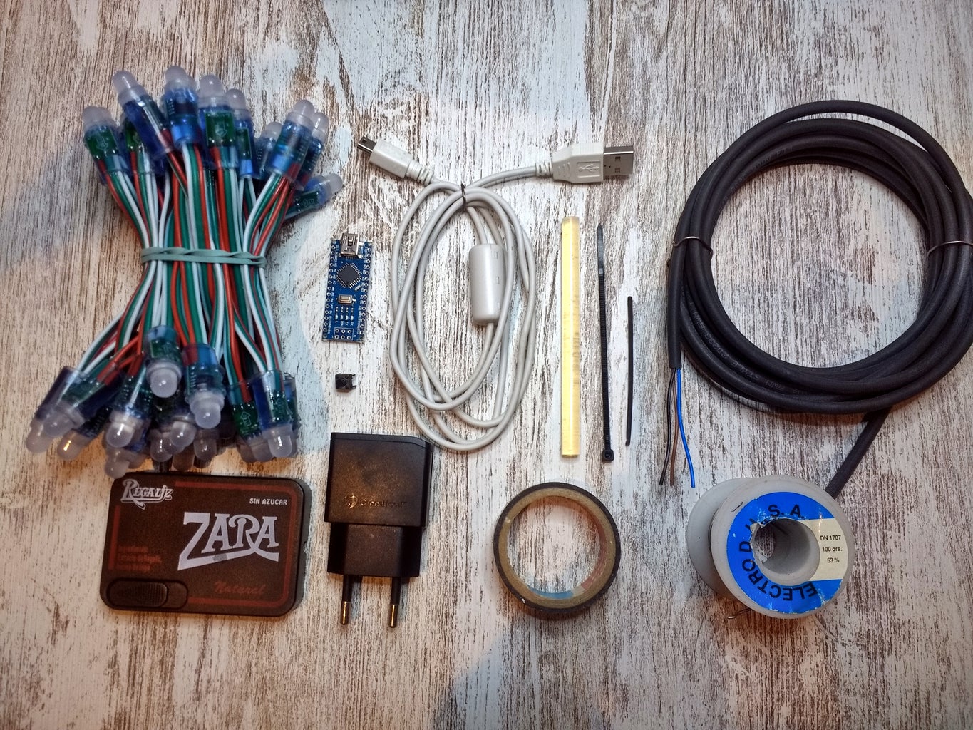
This are the materials I used:
- Arduino nano. I ordered one with pins unsoldered since I soldered cables directly on the board.
- 5V WS2811 50 LED strip There are also with green cables that are more discrete.
- Switch. One with a long button is better.
- USB charger. A used one from a cellular phone.
- USB Cable type A male <-> type mini-B male. Reused from an old camera.
- Plastic box. Reused a candy one.
- A cable tie.
- Three-wire cable.
- Soldering tin.
- Glue for the glue gun.
- Insulating tape
- Heat shrink tube
Tools Used
Drill, drill bit. Glue gun. Soldering iron. Scissors.
- Drill, drill bit.
- Glue gun.
- Soldering iron.
- Scissors.
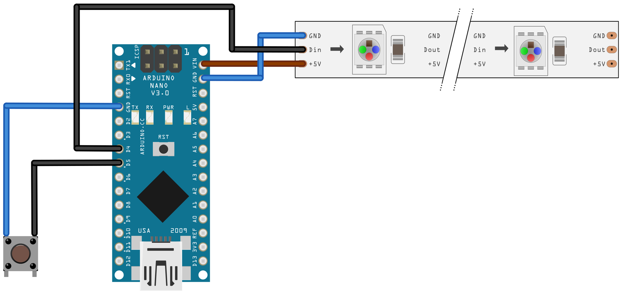
Schematic
It is connected to GND because we use the internal pull-up resistor in Arduino to avoid false signals. Then in code a 1 will be no pulsated, and 0 pulsated.
Power
We will power everything through the USB connector. The led strip will be powered through the VIN pin for not overloading the voltage regulator.
LED Strip
There are many types of addressable LED strips. The ones based in WS281x are very common. This chip family makes the Pulse Width Modulation (PWM) for you for each color, based on the data received in the data input pin. It uses the first block of data with every color and pushes the rest of the data flow to the next chip trough the data out pin. Fortunately, there are Arduino libraries that make all this work transparent for you.
Microcontroller
Since the WS2811 LED strip needs a 5V data input we choose an Arduino with 5V logic. A 3.3V one could also be used, but we should make some sort of logic level adaptation. If not, it could work but a little voltage drop could drive to incorrect data or no data at all arriving at the LED strip.
Simpler microcontrollers as ATtiny85 could be used if you want to cut more the cost. Since we only need 1 output and one input. Depending on the versions the flashing is more difficult if it does not have a USB port.
Switch
One with a long button will suit better to go through the case, then you can actuate it without a pencil.
It is connected to GND because we use the internal pull-up resistor in Arduino to avoid false signals. Then in code a 1 will be no pulsated, and 0 pulsated.
Case Machining
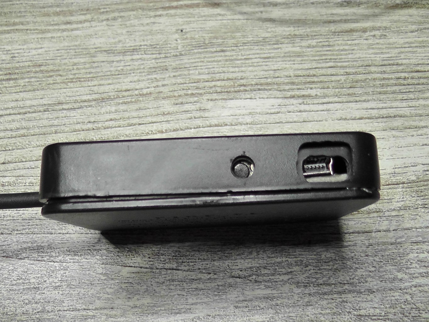
A hole for accessing the switch button. Machine hole for the USB connector. Cable output for the LED strip. In the cover mechanize it till the border in order to remove the cover.
I used a Candy box as the enclosure for the electronics. Use or even 3dPrint one that has enough space.
Just drill it with a Dremel multi-tool. I used a 3mm drill bit for:
- A hole for accessing the switch button.
- Machine hole for the USB connector.
- Cable output for the LED strip. In the cover mechanize it till the border in order to remove the cover.
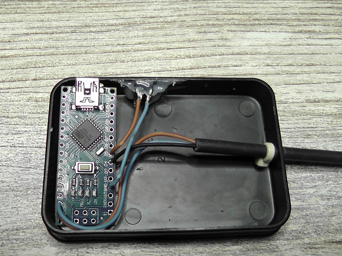
Wiring
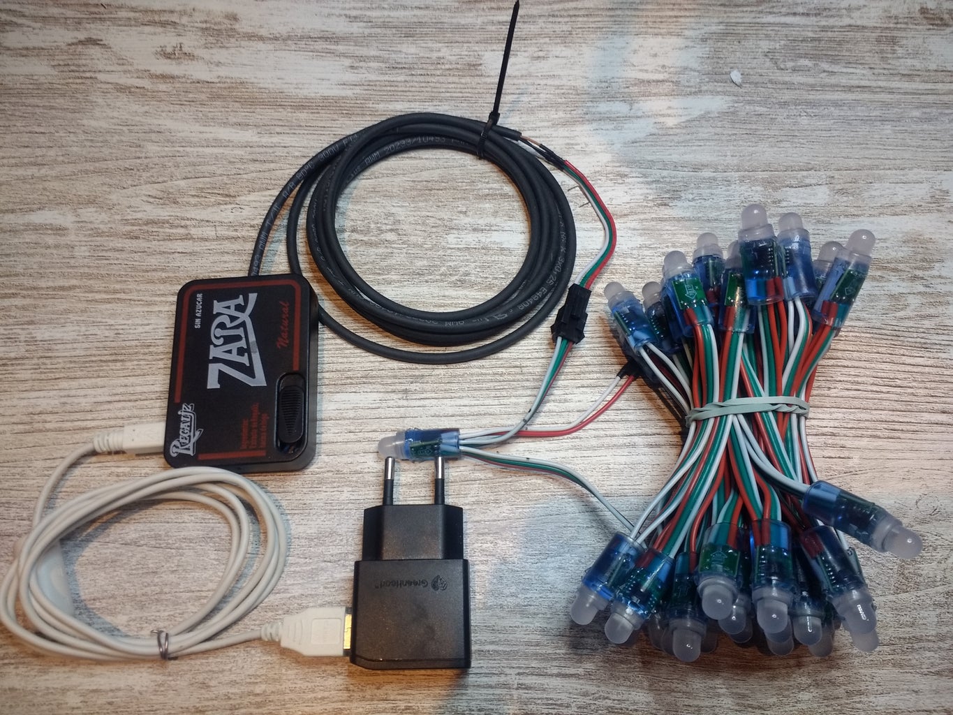
Finally, connect all the connectors.
Soldering
Tips from my own experience.
- Pre tin wires tips first
- Once the wire is in the soldering pad, added tin should be fused by the wire and the soldering pad, not the soldering iron.
Button
Wire the button to input D5 and GND.
The one I used has four pins. They are internally connected by pairs, check before with tester (or a led with a battery) which ones are opened.
Cable
Solder at one end a male connector for the led strip. You can use the one in the LED strip, that we will not use.
- Red (+5V) -> Brown
- Green (data in) -> Black
- White (Gnd) -> Blue
- Brown -> VIN
- Blue -> GND
- Black-> D4
LED Strip
The LED Strip has two three-pin connectors, the input one is the female one. There are red and white cables with no connector that should be insulated with insulating tape or a heat shrink tube to avoid a short circuit.
Microcontroller
Just solder pre-tinned cables in soldering pads,
Connectors
Finally, connect all the connectors.
Element Fixing
CablePut a cable tie to avoid that if eventually there is a pull, The soldering is not damaged.
Button To fix the button I used a glue pistol, put a generous amount and be careful not to glue the button mechanism. I had to do twice since the first time there was so little glue that when we pressed the button it glued off.
MicrocontrollerIt is not fixed.
CablePut a cable tie to avoid that if eventually there is a pull, The soldering is not damaged.
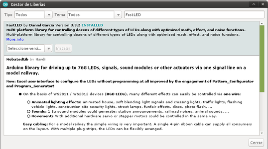
Code
Software Tools and uploading
Usage
Just press the button to change the current animation mode.
Code Download
There is also a multifile class version that you can try.
Tips to make a new animation.
- Create a new method of your choice.
- Increase the total number of animations (MAX_MODES) by one.
- Modify AnimationUpdate for the new case.
Step 8: Revisions
- 24.12.2019 Added video.
- 25.12.2019 Changed Cover picture, orthography corrections.
- 26.12.2019 Added source file.
- 21.11.2020 Updated broken links