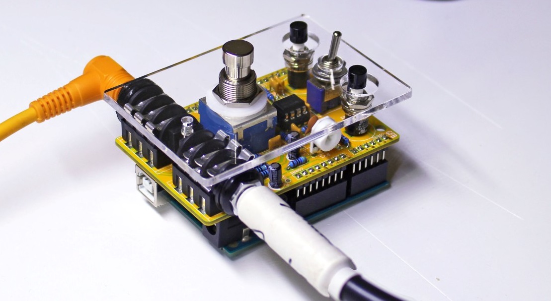
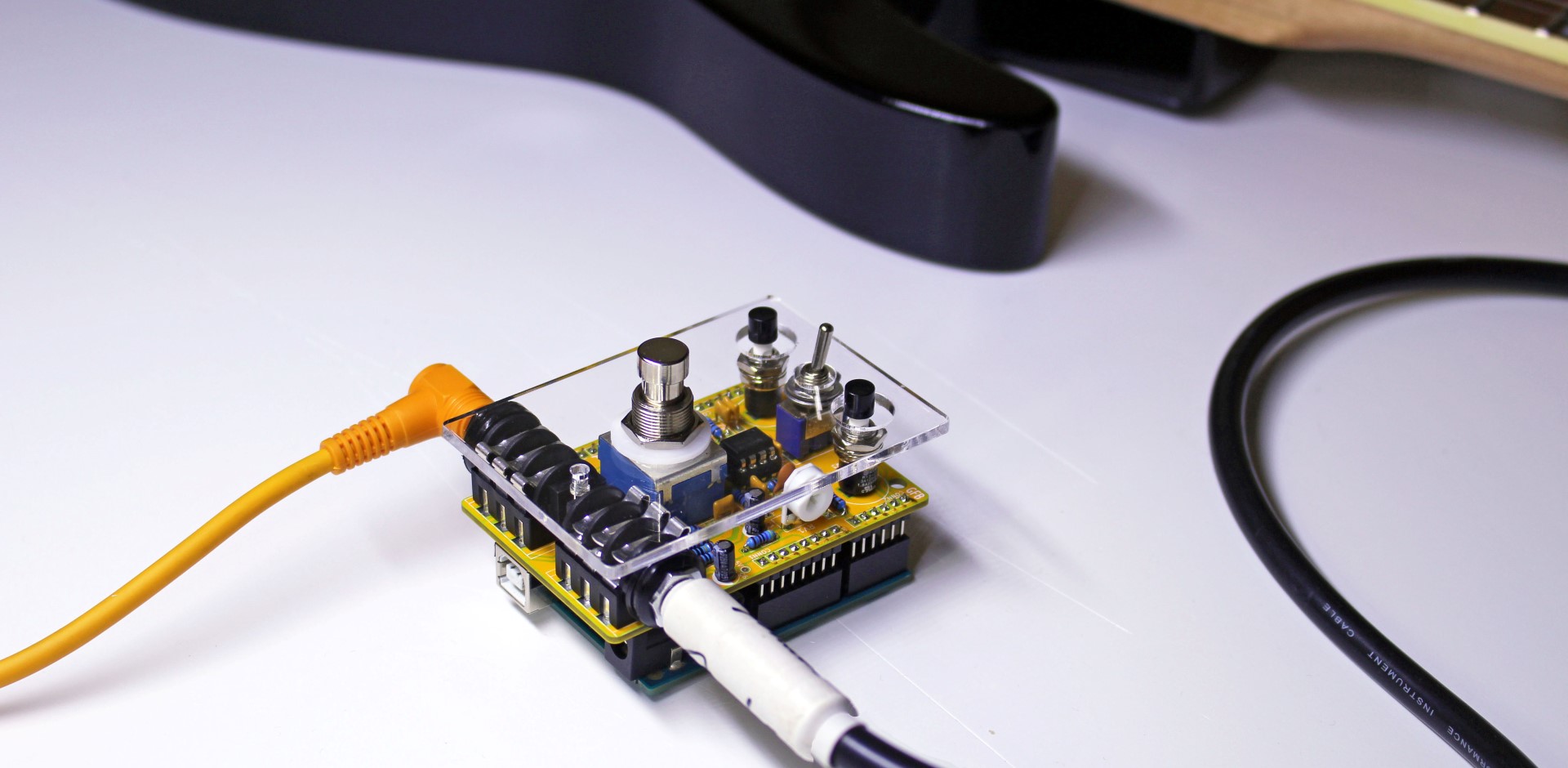
pedalSHIELD UNO is an Arduino UNO programmable guitar pedal. You can create your own guitar effects and digital sounds.
pedalSHIELD UNO is an Arduino UNO programmable guitar pedal. You can create your own effects and digital sounds.
Circuit Parts:
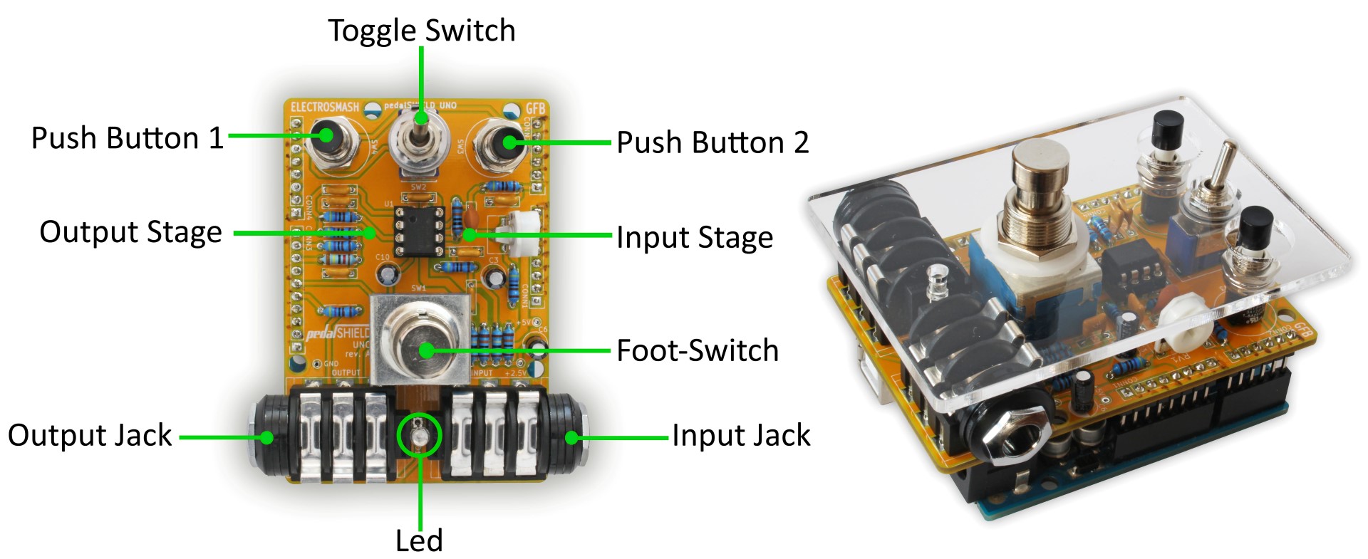
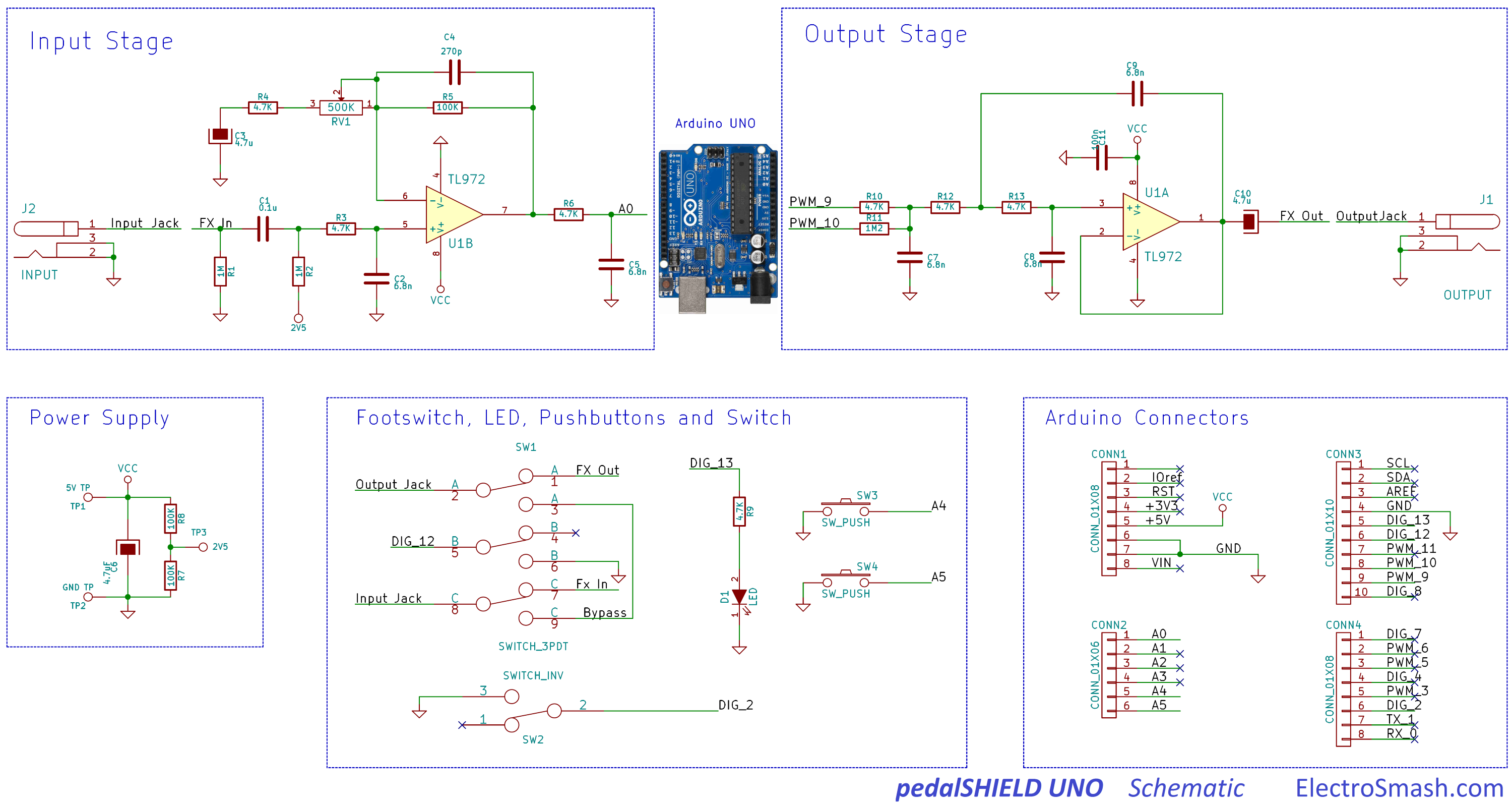
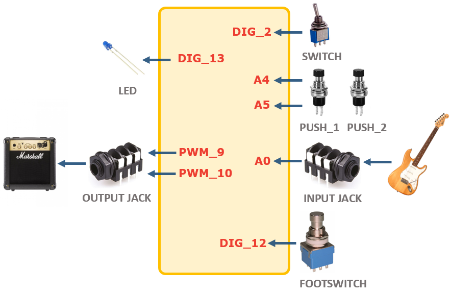
The shield has three parts:
The Input Stage: Amplifies and filters the guitar signal making it ready for the Arduino Uno ADC (Analog to Digital Converter).
Arduino Board: It takes the digitalized waveform from the ADC and does all the Digital Signal Processing (DSP) creating effects (distortion, fuzz, volume, metronome...).
The Output Stage: Once the new waveform is created, the signal is taken from the Arduino digital outputs (two PWMs combined) and prepared to be sent to the next pedal or the guitar amp.
How to Progam it
The idea is to make it as easy as possible, the shield is programmed in C/C++ using the standard Arduino functions and software platform (Linux/Windows/Mac). All tools and programs are free/open source.
Basic knowledge of C is needed. The best way to illustrate how to program it is showing a simple example pedal with a Volume/Booster effect:
// CC-by-www.Electrosmash.com
// Based on OpenMusicLabs previous works.
// pedalshield_uno_booster.ino: pressing the pushbutton_1 or 2 turns the volume up or down.

//defining harware resources.
  #define LED 13
  #define FOOTSWITCH 12
  #define TOGGLE 2
  #define PUSHBUTTON_1 A5
  #define PUSHBUTTON_2 A4

//defining the output PWM parameters
  #define PWM_FREQ 0x00FF // pwm frequency - 31.3KHz
  #define PWM_MODE 0 // Fast (1) or Phase Correct (0)
  #define PWM_QTY 2 // 2 PWMs in parallel

//other variables
  int input, vol_variable=512;
  int counter=0;
  unsigned int ADC_low, ADC_high;

  void setup() { //setup IO - inputs/outputs pins configurations and pull-ups
  pinMode(FOOTSWITCH, INPUT_PULLUP);
  pinMode(TOGGLE, INPUT_PULLUP);
  pinMode(PUSHBUTTON_1, INPUT_PULLUP);
  pinMode(PUSHBUTTON_2, INPUT_PULLUP);
  pinMode(LED, OUTPUT);

// setup ADC- configured to be reading automatically the hole time.
  ADMUX = 0x60; // left adjust, adc0, internal vcc
  ADCSRA = 0xe5; // turn on adc, ck/32, auto trigger
  ADCSRB = 0x07; // t1 capture for trigger
  DIDR0 = 0x01; // turn off digital inputs for adc0

// setup PWM - for more info about this config check the forum.
  TCCR1A = (((PWM_QTY - 1) << 5) | 0x80 | (PWM_MODE << 1)); //
  TCCR1B = ((PWM_MODE << 3) | 0x11); // ck/1
  TIMSK1 = 0x20; // interrupt on capture interrupt
  ICR1H = (PWM_FREQ >> 8);
  ICR1L = (PWM_FREQ & 0xff);
  DDRB |= ((PWM_QTY << 1) | 0x02); // turn on outputs
  sei(); // turn on interrupts - not really necessary with arduino
  }

void loop()
{
//Turn on the LED if the effect is ON.
  if (digitalRead(FOOTSWITCH)) digitalWrite(LED, HIGH);
     else  digitalWrite(LED, LOW);
//nothing more here, all happens in the Timer 1 interruption.
}

ISR(TIMER1_CAPT_vect) //Timer 1 interruption.
{
  // read the ADC input signal data: 2 bytes Low and High.
  ADC_low = ADCL; // Low byte need to be fetched first
  ADC_high = ADCH;
  //construct the input sumple summing the ADC low and high byte.
  input = ((ADC_high << 8) | ADC_low) + 0x8000; // make a signed 16b value

// The push-buttons are checked now:
counter++; //to save resources, the push-buttons are checked every 100 times.
if(counter==100)
{
counter=0;
if (!digitalRead(PUSHBUTTON_1)) {
  if (vol_variable<1024) vol_variable=vol_variable+1; //increase the vol
    }
if (!digitalRead(PUSHBUTTON_2)) {
  if (vol_variable>0) vol_variable=vol_variable-1; //decrease vol
    }
}

//the amplitude of the signal is modified following the vol_variableusing the Arduino map fucntion
  input = map(input, 0, 1024, 0, vol_variable);

//write the PWM output signal
  OCR1AL = ((input + 0x8000) >> 8); // convert to unsigned, send out high byte
  OCR1BL = input; // send out low byte
}
Links and Important Info:
