Numerous studies have shown that flickering, Although high frequency and then totally invisible, It can also cause headaches, eyestrain...
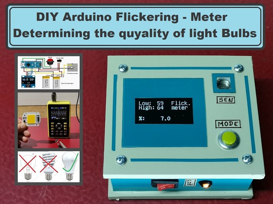
This time I will sho you how to make a device that can determine the quality of the bulbs, from the point of view of their flicker. The quality also depends on the spectrum of light they emit, but we will discuss this in one of the following videos.
Incandescent, halogen or fluorescent lamps (as well as LED if poorly designed), turn on and off a hundred times a second and produce light with a flicker at a certain frequency.
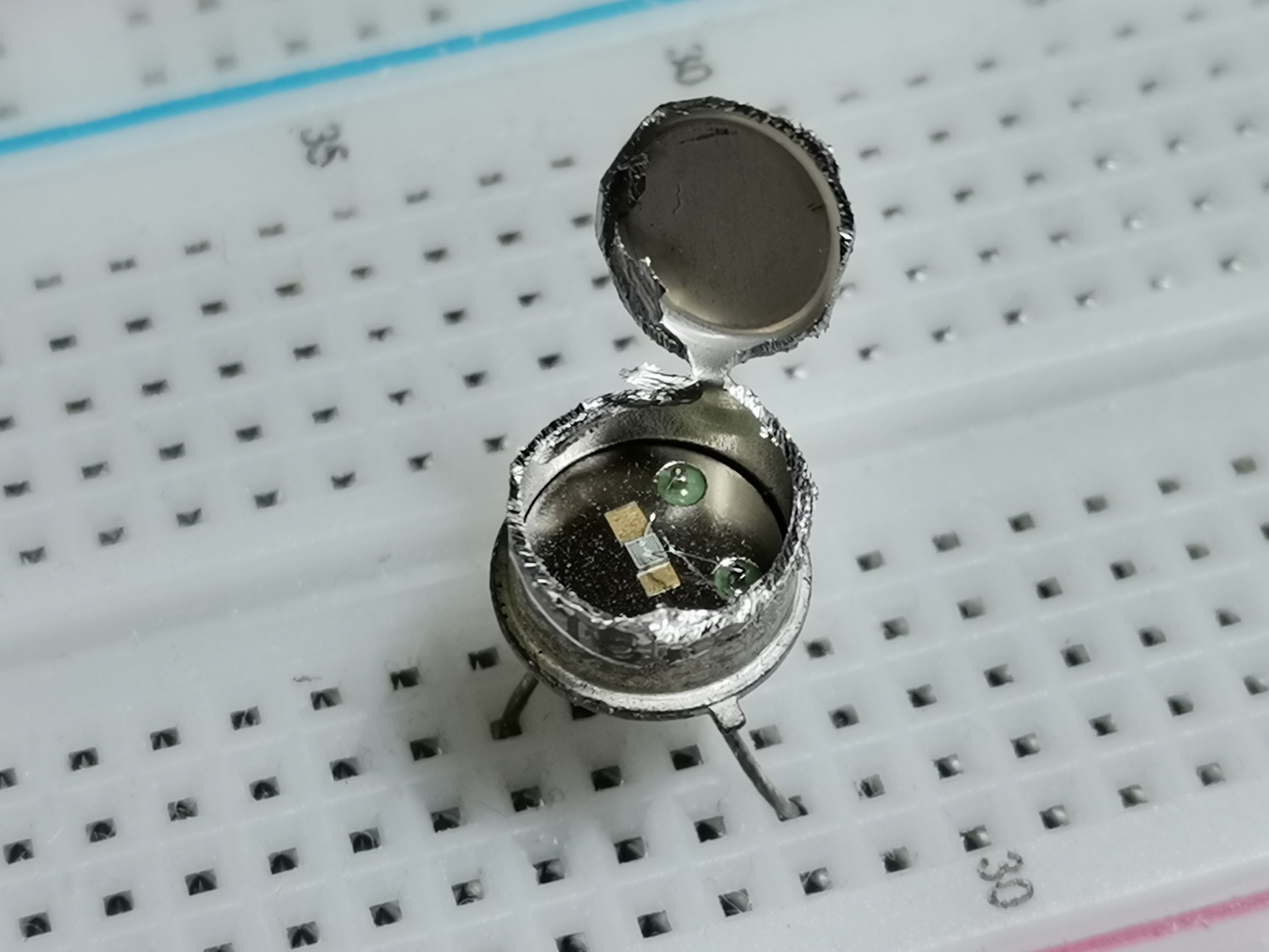
Numerous studies have shown that flickering, Although high frequency and then totally invisible, It can also cause headaches, eyestrain and nausea. Commercial flickering measuring instruments are very expensive (from a few hundred to several thousand dollars), and we can make it for about ten dollars. The code is taken from Electronupdate blog, and instead of APDS9002 ligt sensor I use homemade sensor made of old transistor in metal box BC219. For a sensor you can use almost any transistor with a metal housing to which you will cut the upper part. I also use a 1.3 inch OLED display instead of 0.9 inches for better visibility, with minor code changes.
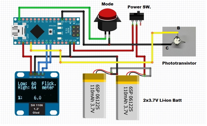
The device is extremely simple to make and contains only a few components:
- Arduino Nano Microcontroller
- Small 1.3 inch Oled Display with SH 1106 chip
- homemade Light sensor made of an old metal transistor
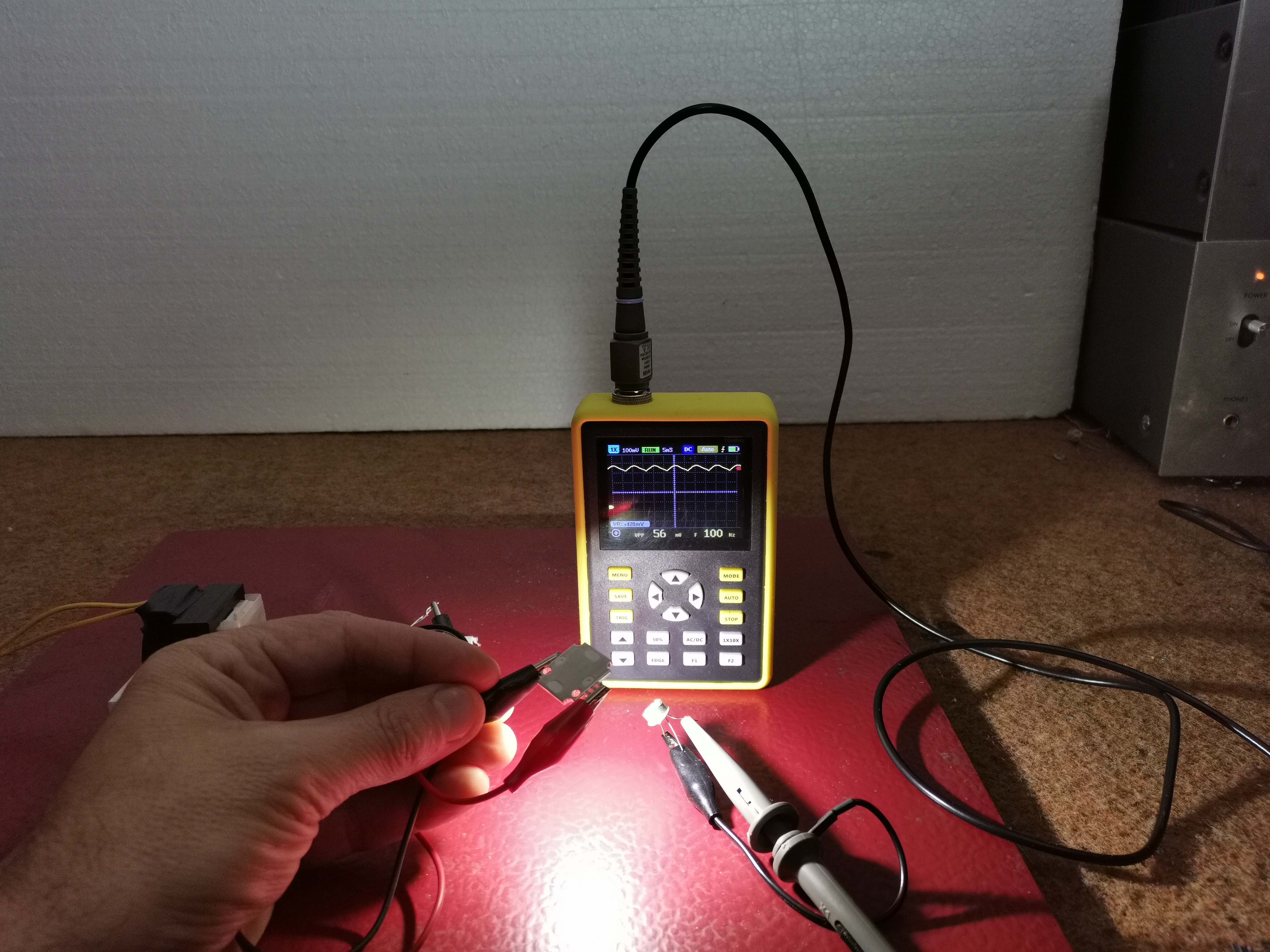
If we have an oscilloscope, there is a very simple way to test the flickering period and amplitude. All we have to do is connect the sensor directly to the scope without any additional electronics. Due to the nature of the experiment, the light during the shooting can change from very weak to very strong. We will first test the brightness of this battery flashlamp. As we can see, the signal is in the form of a straight line, which is logical considering that the LED is powered by direct current from the battery. Next we will test several types of light sources. I will present it to you in a very general and simplified way so that it can be better understood. In general, the closer the signal shape is to such a straight line, the better the lamp.
The shape of the electricity in the public network has a frequency of 50 Hz (or 60 Hz in some countries). Old incandescent bulbs are powered directly from the mains so they flash at the same frequency of 50Hz, but their flicker is imperceptible because they are actually heaters, and can not quickly follow the change, which in this case is a positive feature, and there is not visible flickering. In some cases, LED bulbs were powered by a half-wave voltage, obtained by using a one diode, and their flicker is at a frequency of 50 Hz and with high intensity, because LEDs are electronic elements that currently monitor the change of voltage, unlike incandescent bulbs. Even today some lamps use this principle, and we should certainly avoid them. Now consider a type of high power LED used in spotlight. In this type of LED, the power supply is located on the cooling plate itself, and probably uses the "pulse width modulation" principle without a filter capacitor. As seen on the oscilloscope the signal is almost rectangular with a large difference between the minimum and maximum amplitude. This type of lamp should be avoided in the home, and can only be used for outdoor lighting.
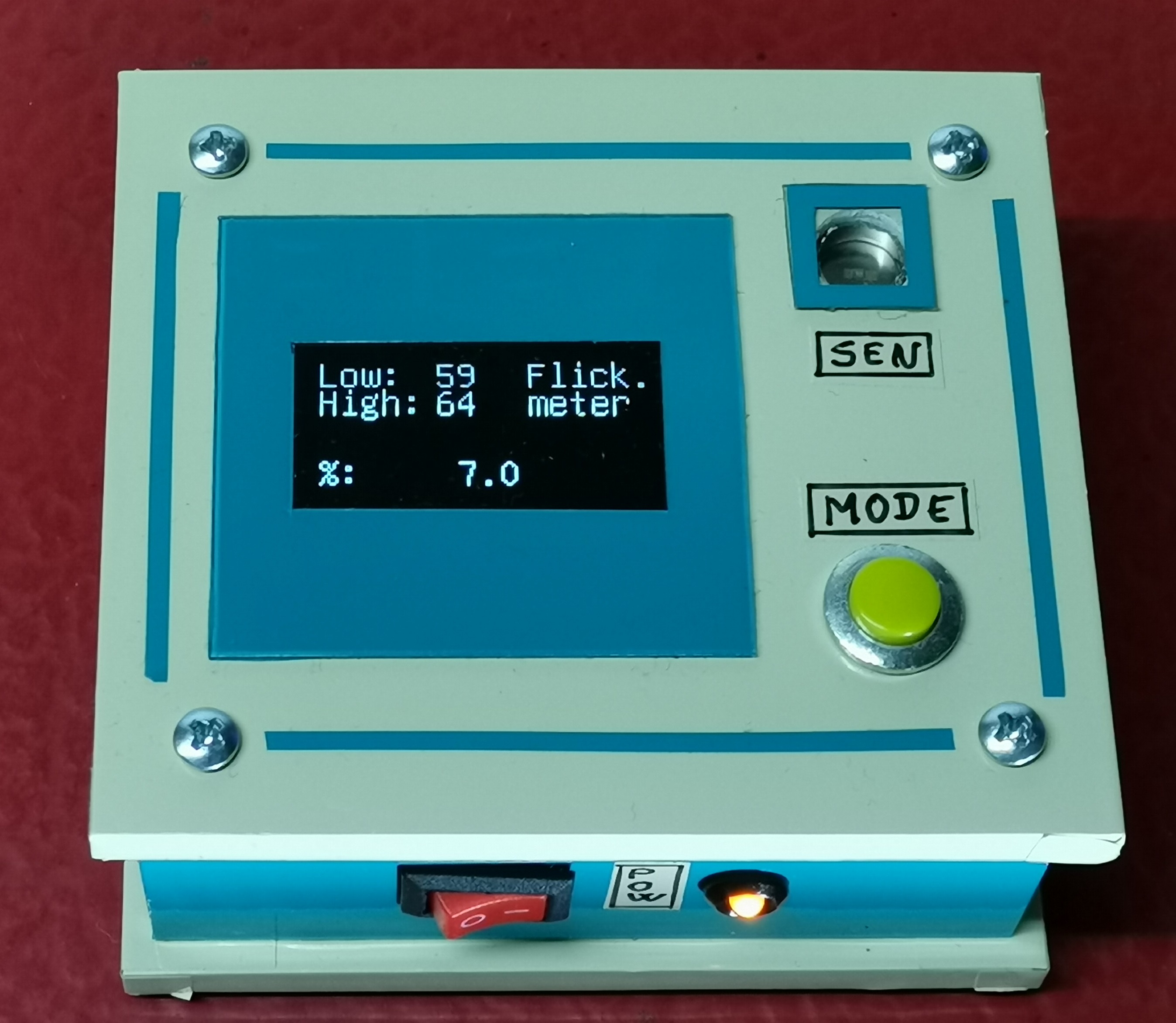
The device I present to you is cheap, compact and shows the degree of flickering in percent, and there is also an oscilloscope mode where we can see the shape of the light signal. It is practical because it is powered by batteries so that we can freely walk around any room and measure the percentage of flicker of light sources. In the video you can see more types of lamps (Bulbs) as well as their characteristics in terms of flicker.
Finally, the device is placed in a suitable small case made of PVC material with a thickness of 5 mm and coated with self-adhesive colored wallpaper.
// flicker_meter
//   compute flicker index
// Sketch is for illustrative purposes only  The sketch is  provided as is without any guarantees or warranty or suitability to purpose.
//
// [email protected]
//
//  dependencies:
//  - u8glib required for driving OLED display
//  - Ardunio Nano rev 3
//  - 128 x 64 OLED display. i2c interface... "heltec.cn"
//  - 1 push button switch
//  - Light sensor
//  - extrernal vref

#include "U8glib.h"
#include <Wire.h> //I2C Arduino Library
#include "TimerOne.h"

U8GLIB_SH1106_128X64 u8g(U8G_I2C_OPT_NONE); // I2C / TWI ** this is specific to the OLED panel in use... refer to google's library to select different (huge # of panels supported!)

bool display_mode = 0;   //when in mode zero it shows numeric results, when in mode one, graphically
int processed = 0; // zero if sample buffer consumed otherwise 1
int cycle;
int inPin1 = 12;
int inPin2 = 11;
int inPin3 = 10;
int button1, button2, button3;
int control_pin = 3;
int i;
int sample_buffer[129];
int sample_pos = 0;
int full_flag = 0;
int sample_min = 1023;
int sample_max = 0;
int min_final = 1023;
int max_final = 0;
int light_sample = 0;
float percent_flicker = 0;
float scale_factor;


void draw(void) {
  // graphic commands to redraw the complete screen should be placed here
  char temp[50];
  char temp1[50];
  char temp2[50];
  u8g.setFont(u8g_font_unifont);

      percent_flicker = ((max_final - min_final)* 100/(max_final ));

      //noise filter... at really dark levels to prevent error readings of 100% flicker
       if (min_final<1)                    //if ((max_final - min_final) < 4)
        { percent_flicker = 0;
        }
if (display_mode == 0)
  {


    // convert numbers into strings so they can  be displayed
      // adriundo or u8g lib never implemented sprintf
      sprintf(temp1,"%d",min_final);
      sprintf(temp2,"%d",max_final);
      dtostrf(percent_flicker,4, 1, temp);
      u8g.drawStr(0,15, "Low:");
      u8g.drawStr(0,27, "High:");
      u8g.drawStr(0,57, "%: ");
      u8g.drawStr(45,15, temp1);
      u8g.drawStr(45,27, temp2);
      u8g.drawStr(45,57,temp);
      sprintf(temp,"%d",display_mode);
      u8g.drawStr(80,15, "Flick.");
      u8g.drawStr(80,27, "meter");
      // keyboard check code, uncomment to display key press state
      //if (button1 == 0) {u8g.drawStr(80,10,"1");} else {u8g.drawStr(80,10,"0"); };
      //if (button2 == 0) {u8g.drawStr(90,10,"1");} else {u8g.drawStr(90,10,"0"); };
      //if (button3 == 0) {u8g.drawStr(50,30,"1");} else {u8g.drawStr(50,30,"0"); };
   }

 else
  {
    if (max_final-min_final > 63)

    {scale_factor = (float) 63/(max_final - min_final);}
    else
    {scale_factor = 2;}
    //scale_factor = 1;
    for (i = 0; i < 127; i++)
       {
        u8g.drawPixel(i,(double) (scale_factor * (float)(sample_buffer[i]-min_final)));

    }


  };

}

void setup(){
 // some control buttons
  pinMode(inPin1, INPUT_PULLUP);  //delay time down
   pinMode(inPin2, INPUT_PULLUP);  //delay time up
  pinMode(inPin3, INPUT_PULLUP);  // arm system
  pinMode(A0, INPUT);

  analogReference( EXTERNAL);


  Timer1.initialize(100); // timer running at 0.1 ms (i.e. 10KHz sample rate
  Timer1.attachInterrupt (timerIsr);

    //setup oled screen
  if ( u8g.getMode() == U8G_MODE_R3G3B2 ) {
    u8g.setColorIndex(255);     // white
  }
  else if ( u8g.getMode() == U8G_MODE_GRAY2BIT ) {
    u8g.setColorIndex(3);         // max intensity
  }
  else if ( u8g.getMode() == U8G_MODE_BW ) {
    u8g.setColorIndex(1);         // pixel on
  }
  else if ( u8g.getMode() == U8G_MODE_HICOLOR ) {
    u8g.setHiColorByRGB(255,255,255);
  }

}

void timerIsr()
{
  if (processed == 1)
  {
   light_sample = analogRead(0);

   sample_buffer[sample_pos] = light_sample;

   if (light_sample < sample_min)  sample_min = light_sample;
   if (light_sample >sample_max )  sample_max = light_sample;

   sample_pos++;

   if (sample_pos == 128)
      {
        sample_pos =0;
        min_final = sample_min;
        max_final = sample_max;

        sample_min = 1023;
        sample_max = 0;
        processed = 0;  // set a flag telling main routine there is a data set to process
      }

  }

}


void loop(){

// inint oled


  button1 = digitalRead(inPin1);
  button2 = digitalRead(inPin2);
  button3 = digitalRead(inPin3);

  if (button1 == 0) { display_mode = display_mode ^ 1;
             delay(100);
           } // toggle between numeric and graphic

  u8g.firstPage();
   do {
            draw();

      }  while( u8g.nextPage() );

processed = 1;
 delay(100);

}