This project shows you how you can build a digital code lock with Arduino and Qwiic.
Build a digital code lock device with Arduino and Qwiic system using Zio M Uno and a Hex 4x3 Matrix Keypad.
Project Overview
For this project, we will build a simple digital code lock that users can enter and key in. In this tutorial, we will show users how a digital code lock system works in an Arduino Interface.
By the end of this tutorial you will be able to :
- Set up a digital code lock with Zio and basic 12 keys keypad
- Be able to interface with Arduino IDE to program Zio with keypad
- Create a program that asks users to enter a six-digit password to unlock
- Be able to create a new six-digit password
Helpful Resources
For simplicity purposes, this tutorial assumes that you have a full understanding and the know-how on configuring Zio development boards.
For this project, we assume you have already configured Zuino M Uno to interface with Arduino IDE. If you haven't done so we have a separate post on our development board guides. Check them out below:
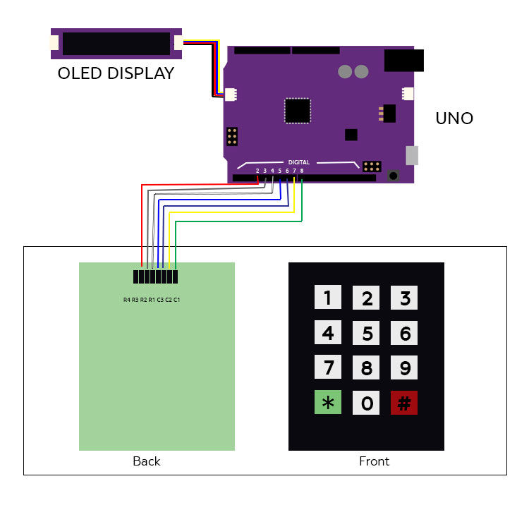
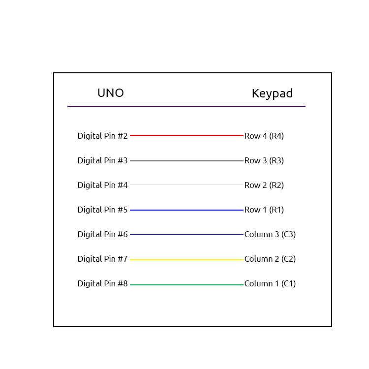
Step 1: Schematic Layout
Step 2: Setup & Configuration
You will need the following modules to build this project:
Step 3
Daisy chain the modules together as shown on the Schematics diagram above.
Daisy chain the modules together as shown on the Schematics diagram above.
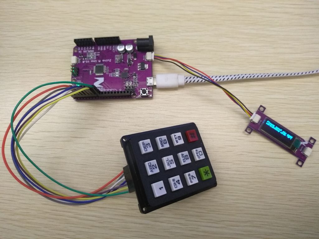
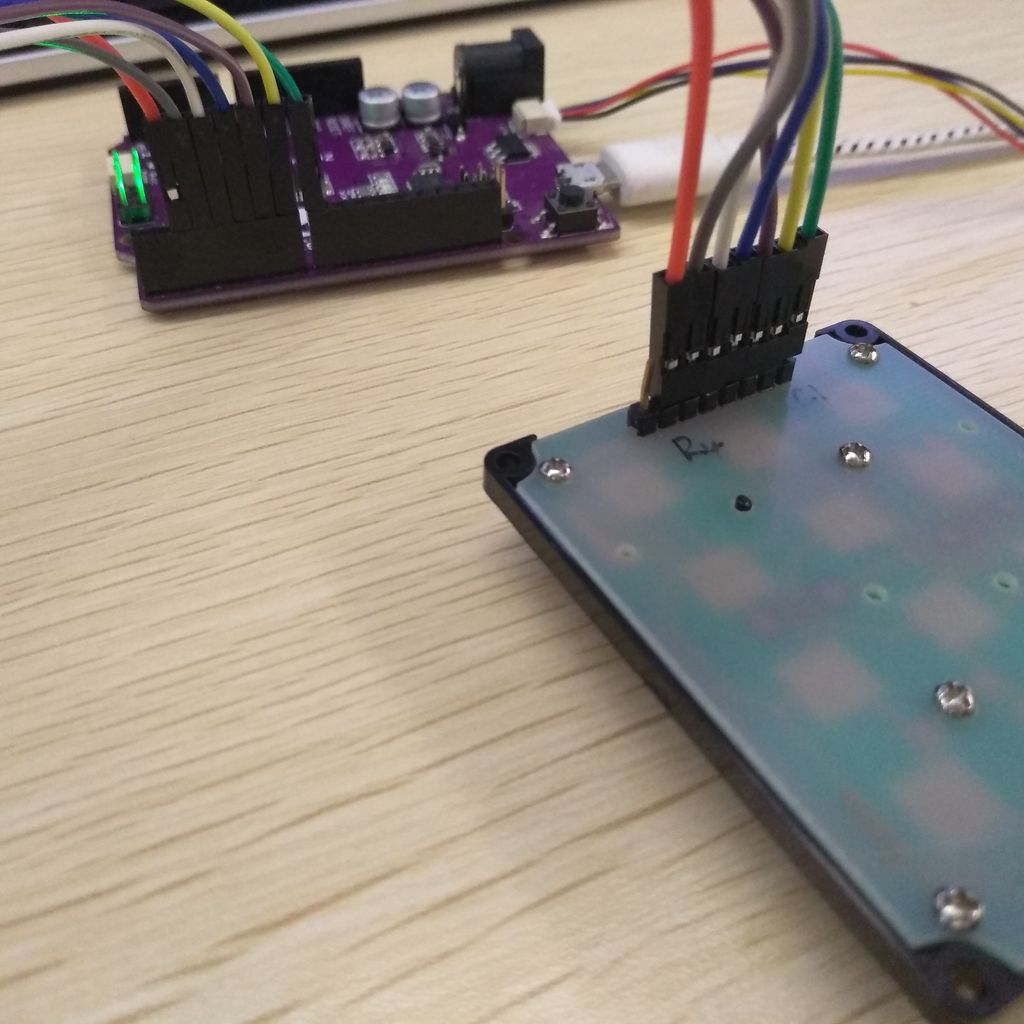
Step 4
Connect the Keypad using Male to Female Jumpers, to your Zuino M Uno
Connect the Keypad using Male to Female Jumpers, to your Zuino M Uno
Step 5: Arduino Libraries
Download and install the following libraries to your Arduino IDE:
Step 6: Downloading the Code
Plug your Uno to a computer. Download and Flash the code to your Uno using the Arduino IDE.
Step 7: Login Test
If you successfully login with the correct password you will see a Welcome screen.
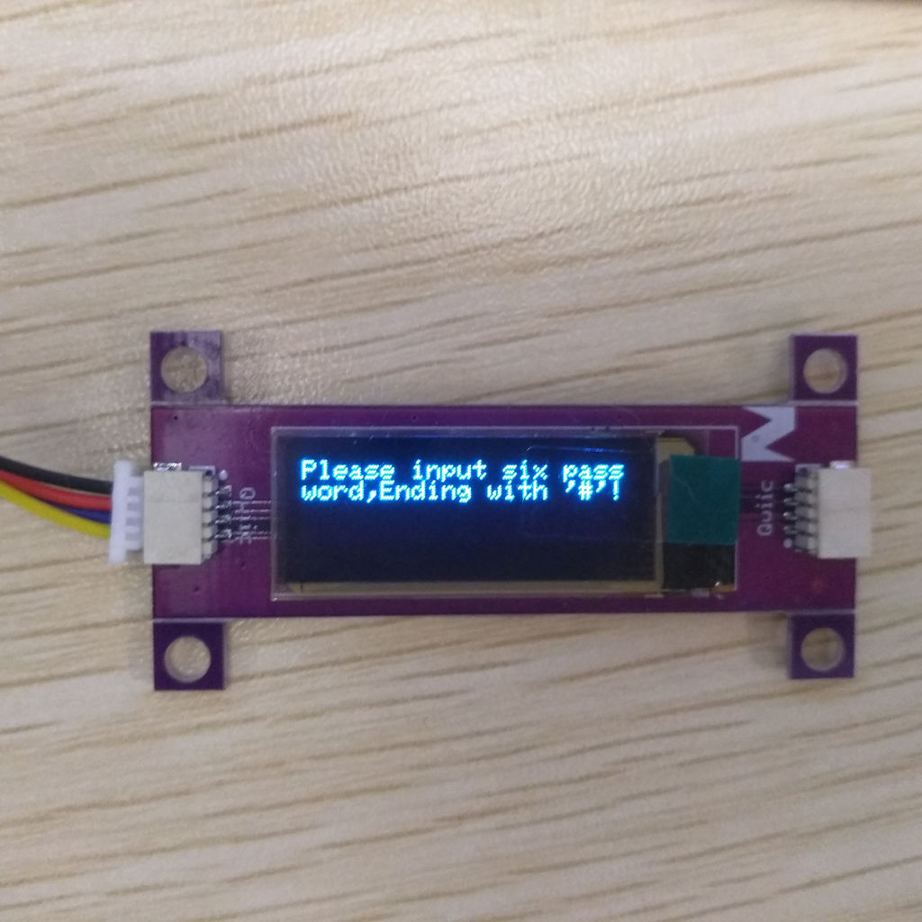
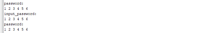
Input the six-digit password followed by the “#” key. To find the 6 digit password stored in the program code, open the serial monitor and it will show the password for the lock.
If you successfully login with the correct password you will see a Welcome screen.
Step 8: Change Password Test
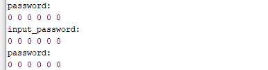
In this example, I changed the password from 123456 to 000000 as shown on the Serial monitor.
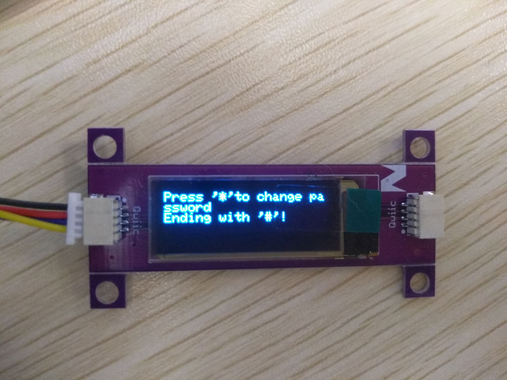
Once you managed to login, you will be able to change the password to a new one. To change the password, confirm it with “*” key.
In this example, I changed the password from 123456 to 000000 as shown on the Serial monitor.
Step 9: Failed Login Attempt Test
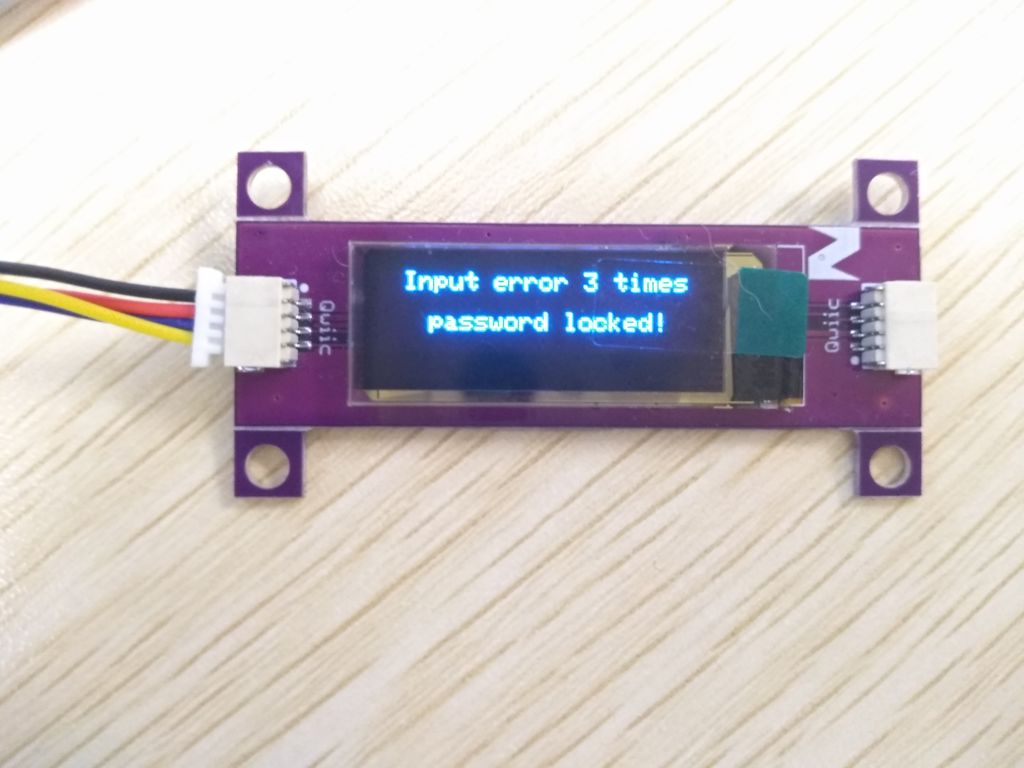
You will be locked immediately after 3 failed attempts.
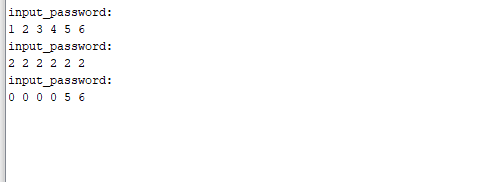
With this demo, we also included the function that, with 3 failed attempts of entering correct password, the device will locked itself. To test it, reset your Uno. Try and enter incorrect password 3 times.
You will be locked immediately after 3 failed attempts.