In this project I made a locker that opens when a correct password is entered.
Introduction
Hello makers. Today we will learn to make an Arduino controlled safe(locker). The main objective of this project was to create a smaller version of commercial password based safes in the market. This is a simple project with keypad, servo and lcd interfacing.
Sponsor Link : UTSource
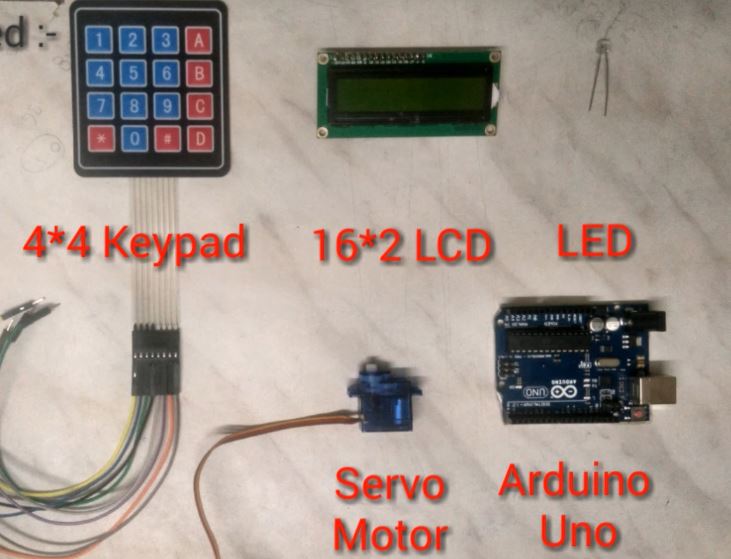
The main components of this project include -
1. Arduino Uno x 1
2. 4*4 Keypad x 1
3. 16*2 Lcd x 1
4. Led x 1
5. Servo motor x 1
6. Header wires
Things you need to make the Safe -
1 Rectangular box
Cutter (for cutting the box)
A door latch
Some copper wire (for connecting the servo to the latch)
Some paint if you want to paint your box. I just went with gift wrap and covered the entire box with it.
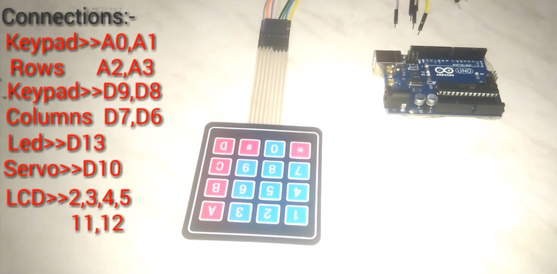
Let's do the connections first -
You can download the circuit diagram from the assets section.
I have divided them into two parts to keep them simple. The first part involves the connection of the keypad, servo motor and led. And the second part shows the connection of the 16 * 2 Lcd. The Keypad Matrix is multiplexed so you need just 8 pins to control the 16 keys. An Led like always is connected to digital pin 13. And a Servo motor is connected to a PWM pin. All the connections are well explained in the the above image above or you can always refer the circuit diagram.
Uploading the code -
*** FIRST DOWNLOAD AND INSTALL THE PASSWORD AND KEYPAD LIBRARIES ***
JUST EXTRACT THEM IN ARDUINO LIBRARIES FOLDER
Install the above mentioned two libraries. You can download them directly from the library manager or you can download the zip file and extract these libraries into the Arduino library. You can find them on the official Arduino's website.
I have attached two programs here. One is to test the keypad and the other is the complete code with password feature. Connect the Arduino to the PC and upload the code to it. Also don't forget to change the servo angle and the password as per your requirement. Once this is done it's time to build the Safe.
// Main Code

/*

***  DON'T FORGET TO DOWNLOAD AND INSTALL THE PASSWORD AND KEYPAD LIBRARIES   ***

                 JUST EXTRACT THEM IN ARDUINO LIBRARIES FOLDER
*/
#include  //http://www.arduino.cc/playground/uploads/Code/Password.zip
#include  //http://www.arduino.cc/playground/uploads/Code/Keypad.zip
#include <LiquidCrystal.h>
#include <Servo.h>
LiquidCrystal lcd(12, 11, 5, 4, 3, 2);
Servo myservo;
Password password = Password( "123" );//CHANGE THE PASSWORD HERE
byte led = 13;
const byte ROWS = 4; // Four rows
const byte COLS = 4; //  columns
// Define the Keymap
char keys[ROWS][COLS] = {
  {'1','2','3','A'},
  {'4','5','6','B'},
  {'7','8','9','C'},
  {'*','0','#','D'}
};

byte rowPins[ROWS] = { A0, A1, A2, A3 };// Connect keypad ROW0, ROW1, ROW2 and ROW3 to these Arduino pins.
byte colPins[COLS] = { 9, 8, 7, 6 };// Connect keypad COL0, COL1 and COL2 to these Arduino pins.


// Create the Keypad
Keypad keypad = Keypad( makeKeymap(keys), rowPins, colPins, ROWS, COLS );

void setup()
{
  pinMode(led, OUTPUT);
  myservo.attach(10);
   digitalWrite(led, LOW); // Turn the LED off
     myservo.write(70);
  lcd.begin(16, 2);
  Serial.begin(9600);
  lcd.print("ENTER PASSWORD");
  lcd.setCursor(0, 1);
  keypad.addEventListener(keypadEvent); //add an event listener for this keypad
}

void loop(){
  keypad.getKey();
}

//take care of some special events
void keypadEvent(KeypadEvent eKey){
  switch (keypad.getState()){
    case PRESSED:
  Serial.print("Pressed: ");
  Serial.println(eKey);
  switch (eKey){
    case 'A': checkPassword(); break;
    case 'C': password.reset(); break;
    default: password.append(eKey);
     }
  }
}

void checkPassword()
{
  if (password.evaluate())
  {
    Serial.println("Success");
    lcd.print("SAFE OPENED");
   myservo.write(110);
    digitalWrite(led,HIGH);
    lcd.setCursor(0, 1);
    lcd.print("");
    password.reset();
  }
  else
  {
    Serial.println("Wrong");
    lcd.print("SAFE CLOSED");
     myservo.write(70);
    digitalWrite(led,LOW);
    lcd.setCursor(0, 1);
    lcd.print("");
   password.reset();
  }
}
// Keypad Test Code :

#include <Keypad.h>
#include <LiquidCrystal.h>
LiquidCrystal lcd(12, 11, 5, 4, 3, 2);
byte led = 13;
const int pass='1';
const byte ROWS = 4; //four rows
const byte COLS = 4; //three columns
char keys[ROWS][COLS] =
{
  {'1','2','3','A'},
  {'4','5','6','B'},
  {'7','8','9','C'},
  {'*','0','#','D'}
};
byte rowPins[ROWS] = {A0, A1, A2, A3}; //connect to the row pinouts of the keypad
byte colPins[COLS] = {9, 8, 7, 6}; //connect to the column pinouts of the keypad

Keypad keypad = Keypad( makeKeymap(keys), rowPins, colPins, ROWS, COLS );

void setup()
{
   pinMode(led, OUTPUT);
   digitalWrite(led, LOW);           // Turn the LED off.
  lcd.begin(16, 2);
  Serial.begin(9600);
   lcd.print("ENTER PASSWORD");
   lcd.setCursor(0, 1);
   keypad.addEventListener(keypadEvent);
}

void loop(){
  char key = keypad.getKey();

  if (key)
  {
    Serial.println(key);
    lcd.print(key);
  }
}
void keypadEvent(KeypadEvent key)
{
    switch (keypad.getState())
    {
    case PRESSED:
        if (key ==pass )
        {
            digitalWrite(led,HIGH);        // Remember LED state
        }
        else{digitalWrite(led,LOW);}
        break;
    }
}
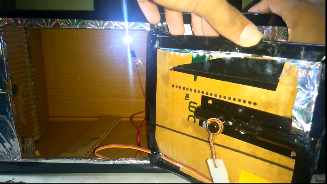
Putting everything together -
I don't have pictures of the making process of the Safe but I can guide you through the steps.
First cut a rectangular piece like I did in the above picture. This acts like a door for your safe. Cut the three sides and leave the fourth side as it is to act as a hinge or you can cut all the four sides and attach one side again with some tape.
Now fix a door latch to the safe's door and connect the latch's holding part to the servo's horn. Use some copper wire or bicycle spoke to do this. Also fix the servo motor on the Safe's door and adjust the length of the copper wire.
Now cut another rectangle for the LCD and fix it in place.
Cut a horizontal slot to just pass the keypad connector inside the box.
Place a led inside the box to show the status(This is optional but it looks cool)
Now fix the Arduino inside with help of some double sided tape.
And then cover the box with some gift wrap to give it a finishing look. You can also add a small knob to the door.
That's it your project is ready.