Use a WS2812B-controlled LED strip to build a thermometer using either an Arduino or Raspberry Pi!
Learn how to use a smart LED strip to build a fancy LED thermometer that mimics the look of an old-style mercury thermometer. I’ll use LEDs with a built-in WS2812B controller IC, meaning each LED can be individually addressed and controlled with an Arduino or Raspberry Pi. This thermometer is a simple and fun project for beginners, and this tutorial describes how smart LED strips work and how you can utilize them in your projects.
Required Hardware
For this project, you'll need:
Preparing the LEDs
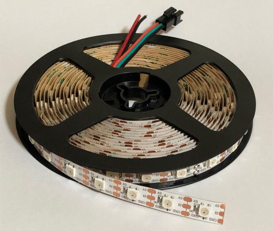
When you order an LED strip with the built-in controller IC, you’ll usually receive a spool with several feet on it that looks something like this:
The LEDs are attached to a flexible PCB that you can cut to the length you need in your project. In this case, it's possible to cut the strip after each LED. Note that this doesn’t always have to be the case. Cheaper RGB-LED tapes (without built-in controller ICs) can sometimes only be cut in multiples of three.
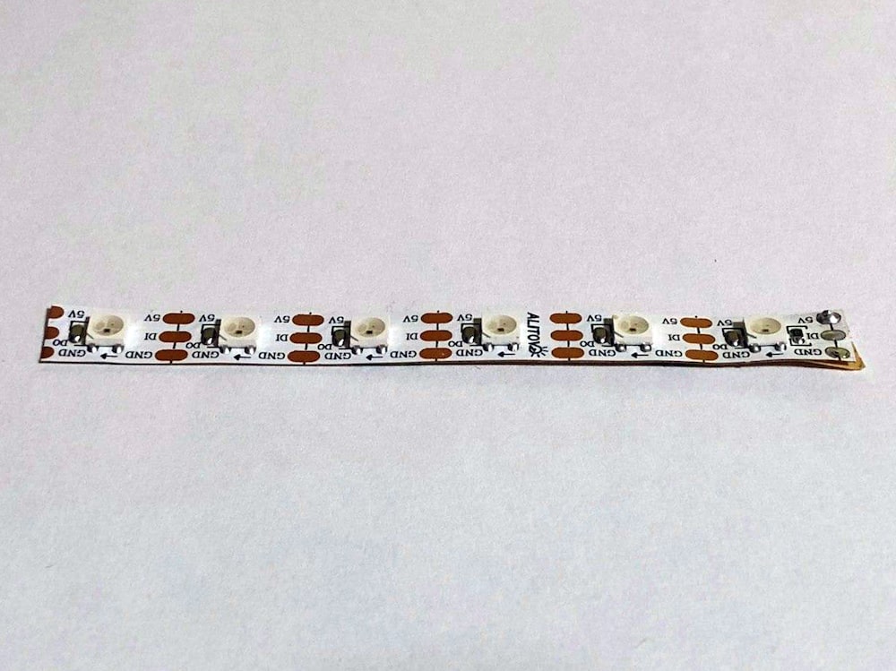
I cut off a small segment that contains six LEDs:
Cut a strip containing six LEDs from the LED spool.
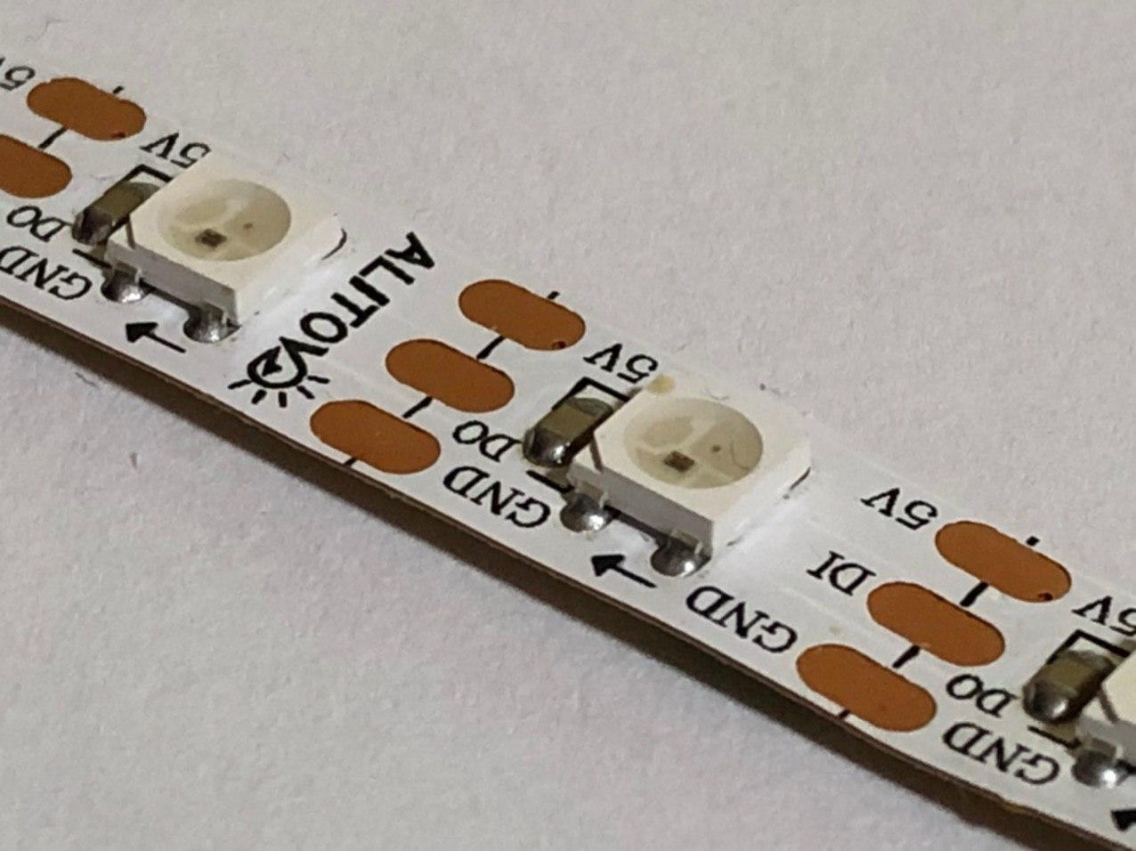
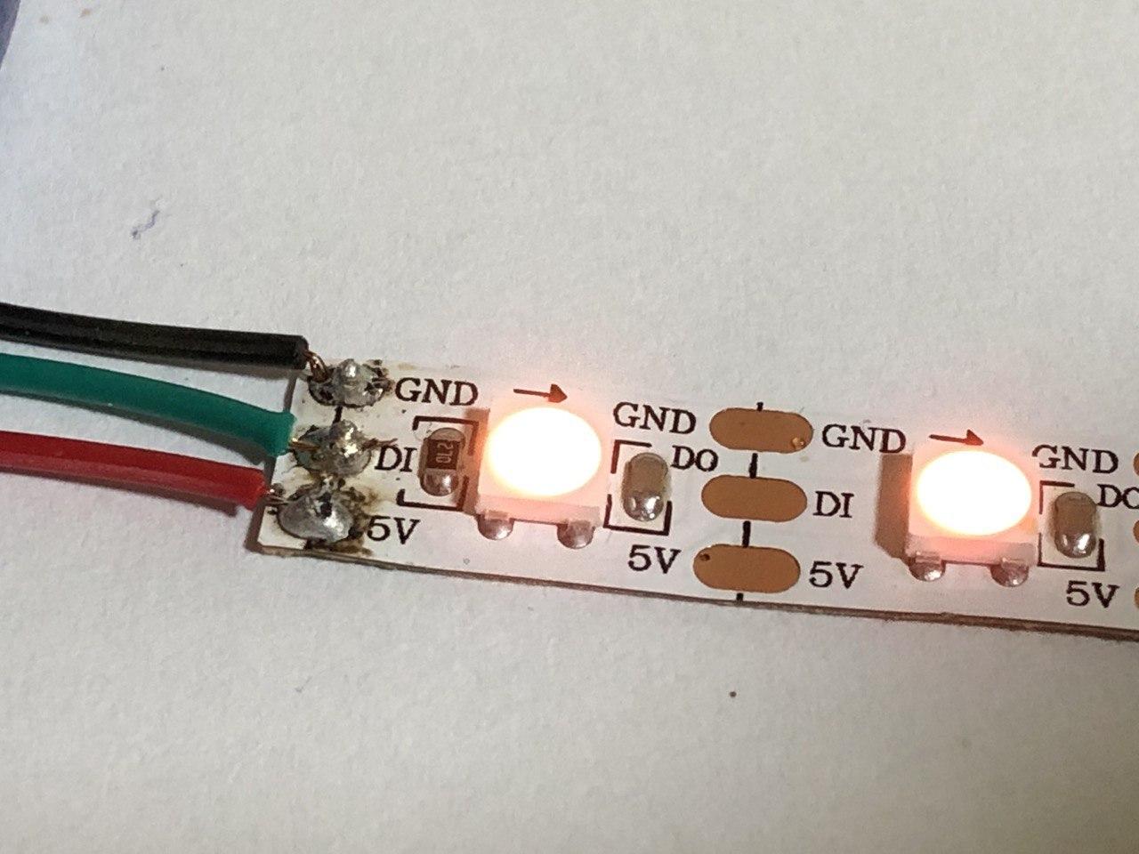
If you take a closer look at the LED strip, you’ll notice an arrow that points towards one end of the strip:
Pay attention to the arrows on the LED strip, which indicate the end of the strip.
The direction is important when you address the LEDs on the strip. The arrow points towards the end of the strip and, therefore, the opposite end has to be connected to the microcontroller.
The Connections of the LED Strip
The LED strip has two power connections you need to connect to the +5V and GND pins of your controller. Note that this is okay for a short LED strip. If you want to control a longer piece, however, you should use an external PSU if the LEDs draw more current than your microcontroller can safely supply. The third connection is a single communication line that controls the LEDs on the flexible PCB.
Solder three wires directly to the pads of the LED strip. Make sure to solder them to the end the arrow is pointing away from (as shown in the image below).
Solder three wires to the GND, 5V, and communication line.
In the next step, the three wires have to be connected to a controller. In this case, I used an Arduino. Note, that it doesn’t matter which output pin you connect the strip’s data wire to. You’ll just have to change a variable in the code later to accommodate for that.
Connecting the LED Strip to the DHT-11 temperature sensor
You’ll have to connect a sensor to the Arduino to be able to determine the temperature in the room. I used a DHT-11 temperature and humidity sensor for that task. You can also use the DHT-22 variant, which is more accurate and works on a greater temperature range.
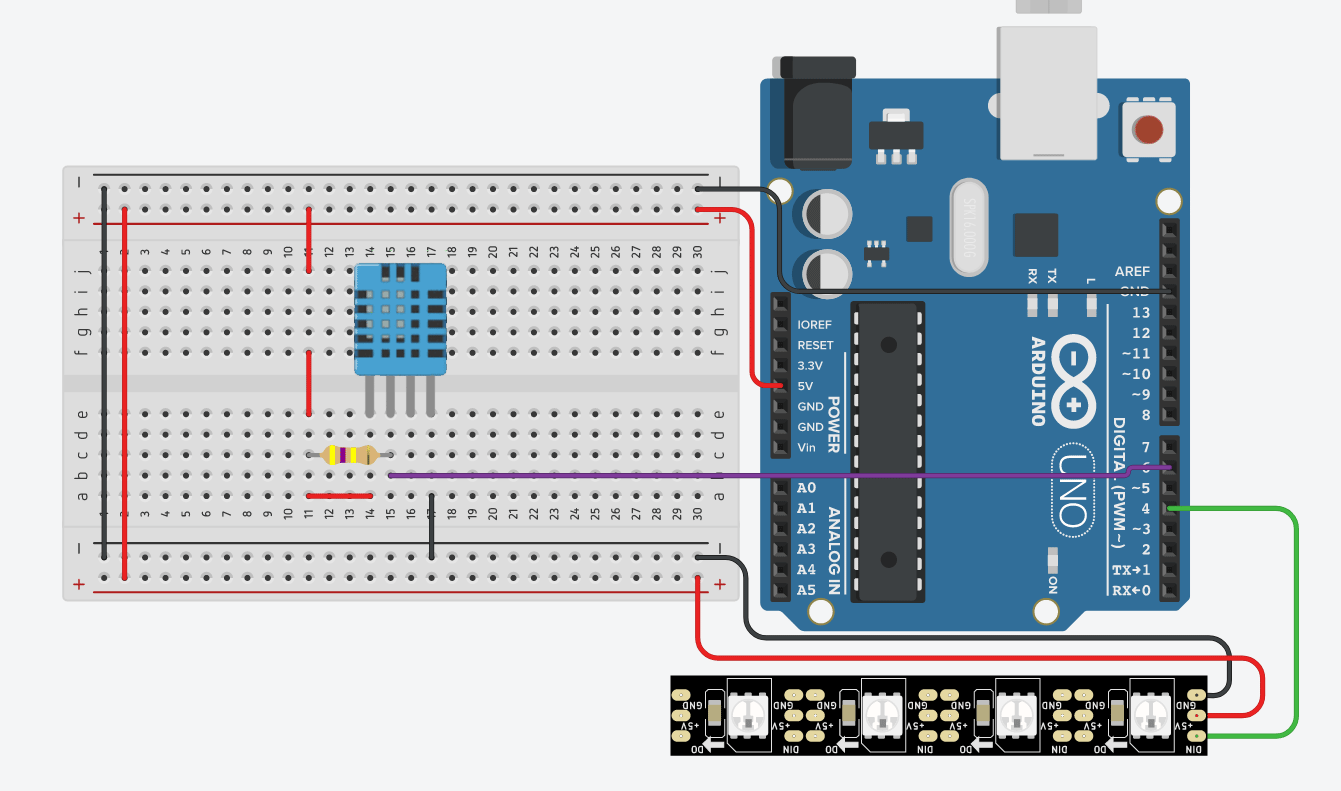
You'll need three wires to connect the temperature sensor to the Arduino. Just like with the LED strip, there are two power lines and a single data-line. The data-line should also be connected to +5V via a pull-up resistor. The resulting circuit for this project looks like this:
The project’s circuit diagram.
The Arduino Software
Luckily, there are pre-made libraries that make it easy to use the DHT-11 and DHT-22 temperature sensors, as well as for the LED strip with an Arduino. The software itself is pretty simple. It only reads the temperature from the sensor and then displays the measured value on the LED strip.
Because the LED strip is quite short, I decided to only display values between 20 and 28 degrees Celsius. However, you can easily adjust that range by changing the displayTemp function.
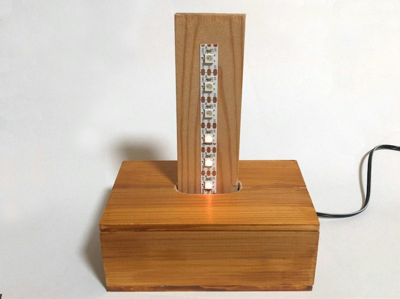
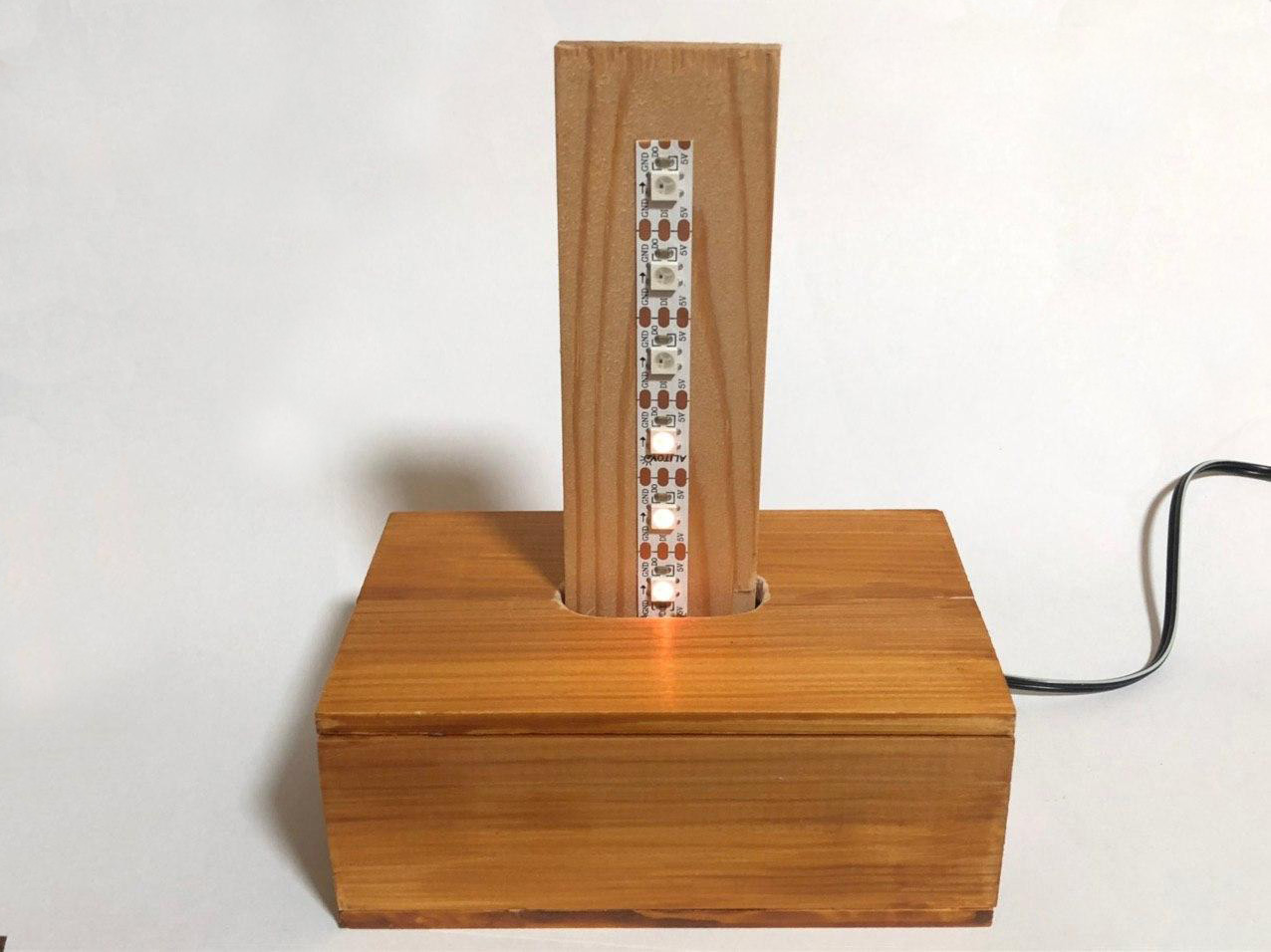
You can download the Arduino sketch at the end of this article. The finished product looks like this:
The completed thermometer.
As you can see, I used a custom wooden enclosure. I took the case design from a project that I made a while ago and added a piece of wood for the LED strip.
Creating the Thermometer With a Raspberry Pi
It’s also possible to use a Raspberry Pi to communicate with the DHT-11 sensor and control the LED strip. If you want to use a Pi, you have to connect the power lines of the LEDs and the DHT-11 sensor. You can directly use the +5V and GND pins of the Raspberry Pi if your LED strip doesn't draw too much current.
Then you must connect the data-line of the LED strip to either GPIO10, GPIO12, GPIO18, or GPIO21. The DHT-11 sensor’s data-line can be connected to any other free GPIO pin.
I also wrote a Python script that reads the temperature from the DHT-11 and then controls the LEDs. It can also be downloaded at the end of this article. It uses the Adafruit Neopixel library and this DHT-11 library for the Raspberry Pi, which can be installed using the following commands:
sudo pip3 install rpi_ws281x adafruit-circuitpython-neopixel adafruit-circuitpython-dht
sudo apt-get install libgpiod2
Make sure to run the script with Python3:
sudo python3 ./led-thermometer.py
This LED thermometer is a fun project for beginners. it doesn’t require complicated wiring, and the software is short and easy to understand. You can play around with it and add more features, or simply place it somewhere and have a decorative and functional thermometer.
Source code files for LED thermometer for Arduino or Raspberry Pi.