Arduino Simulator enables you to showcase your projects for free! 4 way traffic signal project is presented here!
Arduino simulator is used to simulate 4 way traffic signal project is simulated here. This involves a junction where the vehicles can come in 4 different directions. You only need basic components (LEDs) and an Arduino Mega to get started (or nothing, of you are using Wokwi Arduino simulator). You can use this campuses for projects as well as roads where there is congestion. The logic is very simple. I appreciate if you can add more features to this project. I will be happy to publish your code examples too.
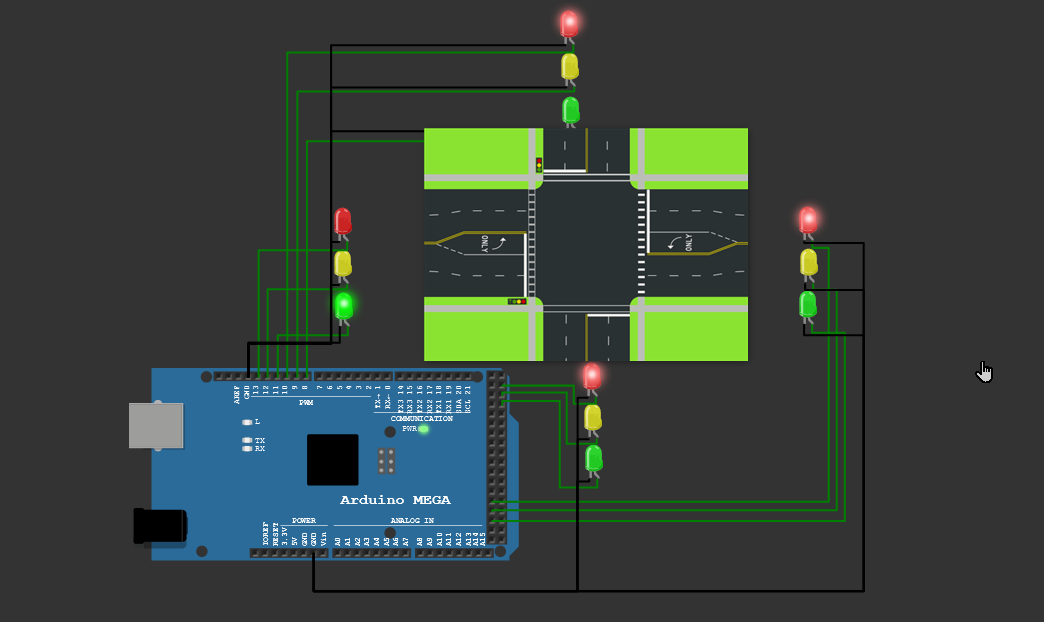
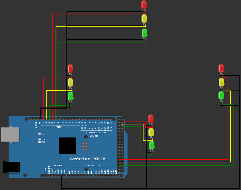
4 way traffic light Arduino Mega Connection diagram
Arduino simulator - 4 way traffic project
Arduino Code for the 4 way traffic light control
int signal1[] = {23, 25, 27};
int signal2[] = {46, 48, 50};
int signal3[] = {13, 12, 11};
int signal4[] = {10, 9, 8};

int redDelay = 5000;
int yellowDelay = 2000;

void setup() {
  // Declaring all the LED's as output
  for (int i = 0; i < 3; i++) {
    pinMode(signal1[i], OUTPUT);
    pinMode(signal2[i], OUTPUT);
    pinMode(signal3[i], OUTPUT);
    pinMode(signal4[i], OUTPUT);
  }
}

void loop() {
  // Making Green  LED at signal 1 and red LED's at other signal HIGH
  digitalWrite(signal1[2], HIGH);
  digitalWrite(signal1[0], LOW);
  digitalWrite(signal2[0], HIGH);
  digitalWrite(signal3[0], HIGH);
  digitalWrite(signal4[0], HIGH);
  delay(redDelay);

  // Making Green LED at signal 1 LOW and making yellow LED at signal 1 HIGH for 2 seconds
  digitalWrite(signal1[1], HIGH);
  digitalWrite(signal1[2], LOW);
  delay(yellowDelay);
  digitalWrite(signal1[1], LOW);

  // Making Green  LED at signal 2 and red LED's at other signal HIGH
  digitalWrite(signal1[0], HIGH);
  digitalWrite(signal2[2], HIGH);
  digitalWrite(signal2[0], LOW);
  digitalWrite(signal3[0], HIGH);
  digitalWrite(signal4[0], HIGH);
  delay(redDelay);

  // Making Green LED at signal 2 LOW and making yellow LED at signal 2 HIGH for 2 seconds
  digitalWrite(signal2[1], HIGH);
  digitalWrite(signal2[2], LOW);
  delay(yellowDelay);
  digitalWrite(signal2[1], LOW);

  // Making Green  LED at signal 3 and red LED's at other signal HIGH
  digitalWrite(signal1[0], HIGH);
  digitalWrite(signal2[0], HIGH);
  digitalWrite(signal3[2], HIGH);
  digitalWrite(signal3[0], LOW);
  digitalWrite(signal4[0], HIGH);
  delay(redDelay);

  // Making Green LED at signal 3 LOW and making yellow LED at signal 3 HIGH for 2 seconds
  digitalWrite(signal3[1], HIGH);
  digitalWrite(signal3[2], LOW);
  delay(yellowDelay);
  digitalWrite(signal3[1], LOW);

  // Making Green  LED at signal 4 and red LED's at other signal HIGH
  digitalWrite(signal1[0], HIGH);
  digitalWrite(signal2[0], HIGH);
  digitalWrite(signal3[0], HIGH);
  digitalWrite(signal4[2], HIGH);
  digitalWrite(signal4[0], LOW);
  delay(redDelay);

  // Making Green LED at signal 4 LOW and making yellow LED at signal 4 HIGH for 2 seconds
  digitalWrite(signal4[1], HIGH);
  digitalWrite(signal4[2], LOW);
  delay(yellowDelay);
  digitalWrite(signal4[1], LOW);
}
Things you need to complete 4 way traffic light project using Arduino simulator
- Arduino Mega
- 4 Red LEDs
- 4 Green LEDs
- 4 Yellow LEDs
- Connecting wires
- Optional (buzzers)
Live project link - 4 way traffic controller using Arduino
Basic working principle of 4 way traffic light Arduino project
There are 4 arrays defined. Four arrays for four traffic poles. The first element in each array corresponds to Red LEDs, Green LEDs, and Yellow LEDs corresponds to the third element in the array.
int signal1[] = {23, 25, 27};
int signal2[] = {46, 48, 50};
int signal3[] = {13, 12, 11};
int signal4[] = {10, 9, 8};
Now, we will initialize all the pins connected to LEDs as output pins. we do it in a for loop as follows
for (int i = 0; i < 3; i++) {
    pinMode(signal1[i], OUTPUT);
    pinMode(signal2[i], OUTPUT);
    pinMode(signal3[i], OUTPUT);
    pinMode(signal4[i], OUTPUT);
  }
One sequence logic is given below. All the other Red LEDs other than pole 1 will be it. The green LED will be lit for pole 1. The yellowDelay and redDelay are constants which can be edited to vary the duration of time for which yellow LED will be on.
/ Making Green LED at signal 1 LOW and making yellow LED at signal 1 HIGH for 2 seconds
  digitalWrite(signal1[1], HIGH);
  digitalWrite(signal1[2], LOW);
  delay(yellowDelay);
  digitalWrite(signal1[1], LOW);
  // Making Green  LED at signal 2 and red LED's at other signal HIGH
  digitalWrite(signal1[0], HIGH);
  digitalWrite(signal2[2], HIGH);
  digitalWrite(signal2[0], LOW);
  digitalWrite(signal3[0], HIGH);
  digitalWrite(signal4[0], HIGH);
  delay(redDelay);
Simulation output
Wokwi Arduino Simulator - Wokwi Arduino Simulator for 4 way traffic signal
Feedback? support? sugestions?
Please leave a comment here or hop-on to Wokwi Discord channel. Thank you and please leave a like, if you found this article useful.