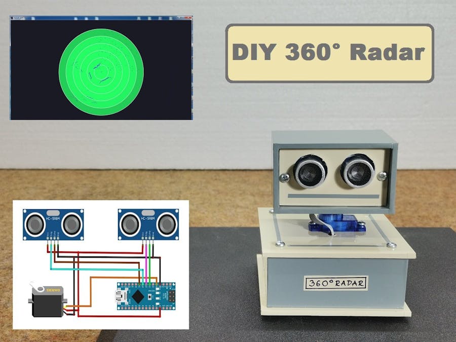
In this case, it is interesting that are used two sensors to scan the entire 360- degree space
This time I will show you how to make Arduino-based ultrasonic radar. We could call it a Sonar because it is using sound, however, sonars are generally considered for use underwater. In this case, it is interesting that are used two sensors to scan the entire 360-degree space. Ultrasonic sensor modules are mounted on a servo motor that rotates between 0 and 180°. This method also simplifies the design because you don’t have the problem of cables getting tangled around the servo.
Head to: https://bit.ly/3DQGHBn to make your PCB. $50 coupon for new users
The process starts with a test of the servo rotation. First, it rotates a 0° to 180° and then 180° to 0° to check the correct movement of the headset. The process starts with a test of the servo rotation. First, it rotates a 0° to 180° and then 180° to 0° to check the correct movement of the headset. The process starts with a test of the servo rotation. First, it rotates a 0° to 180° and then 180° to 0° to check the correct movement of the headset.
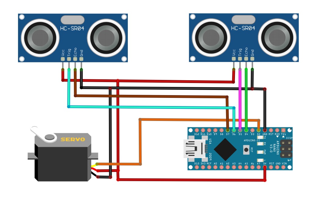
The device is extremely simple to build and consists of several elements:
- Arduino Nano Microcontroller
- and two HC-SR04 Ultrasonic modules
At startup, is tested the movement of the servo motor. Immediately after that, the radar starts scanning. Next, we start the Processing application on the PC, and then we need to enter the correct serial port through which the Arduino communicates. This displays a Radar-like monitor on which the objects are being monitored. Let me mention that the idea and the code are the work of Victor Casado, an Electronics Engineering Student from Spain. It can be seen in the pictures that the device also contains a piezo Buzzer. This is because I am currently testing modified code and depending on the distance of an object, is emitted soundwith a certain frequency. If it succeeds, I will publish the new code in the form of an update.
Finally, the device is built into a suitable box made of PVC board with thicknesses of 3 and 5 mm and coated with self-adhesive colored wallpaper.
#include <HCSR04.h>
#include <Servo.h>

UltraSonicDistanceSensor distanceSensor(6, 7);             //Create the 1st sensor object
UltraSonicDistanceSensor distanceSensor2(5, 4);             //Create the 2nd sensor object
Servo servoMotor;            //Create the Servo object

int delayTime = 5;            //Delay value to wait for the servo to reach the 1 angle difference
long d;                 //Distance from 1st sensor calculated
long d2;                //Distance from 2nd sensor calculated

void setup() {
  Serial.begin(9600);           //Initialize the Serial communication at 9600 bauds

  servoMotor.attach(2);         //Attach the servo to the Digital PWM pin 2
  servoMotor.write(180);        //Rotate the servo to the 180?
  delay(1000);              //Wait for the servo to reach 180?
  servoMotor.write(0);          //Rotate the servo to the 0?
  delay(1000);              //Wait for the servo to reach 0?

}

void loop() {
  for (int i = 1; i < 180; i++) {   //Move the Servo 180 degrees forward
    readSensors();            //Read the sensors
    Serial.print(i);          //Print the angle
    Serial.print(",");          //Print a ","
    Serial.print(d);          //Print the 1st distance
    Serial.print(",");          //Print a ","
    Serial.println(d2);         //Print the 2nd distance with end line
    servoMotor.write(i);        //Set the sensor at the angle
    delay(delayTime);         //Wait for the servo to reach i?
  }
  for (int i = 180; i > 1; i--) {   //Move the Servo 180 degrees backward
    readSensors();            //Read the sensors
    Serial.print(i);          //Print the angle
    Serial.print(",");          //Print a ","
    Serial.print(d);          //Print the 1st distance
    Serial.print(",");          //Print a ","
    Serial.println(d2);         //Print the 2nd distance with end line
    servoMotor.write(i);        //Set the sensor at the angle
    delay(delayTime);         //Wait for the servo to reach i?
  }
}

void readSensors() {
  d = distanceSensor.measureDistanceCm();
  d2 = distanceSensor2.measureDistanceCm();
}


