Assembly instructions for the Android Things Developer started kit released by google.
What is Android Things?
Android Things is a platform released by Google with the Maker community in mind.
The Android Things Developer starter kit is one of several kits released that uses the Android Things platform. This particular kit is designed to allow users to
This article will outline and demonstrate the assembly instructions for the Android Things Developer starter kit. Take a look and see if this kit is interesting to you for future projects.
If you're not sure if you're up for using this platform, this article will outline the assembly instructions for the Android Things Developer starter kit.
Putting It All Together
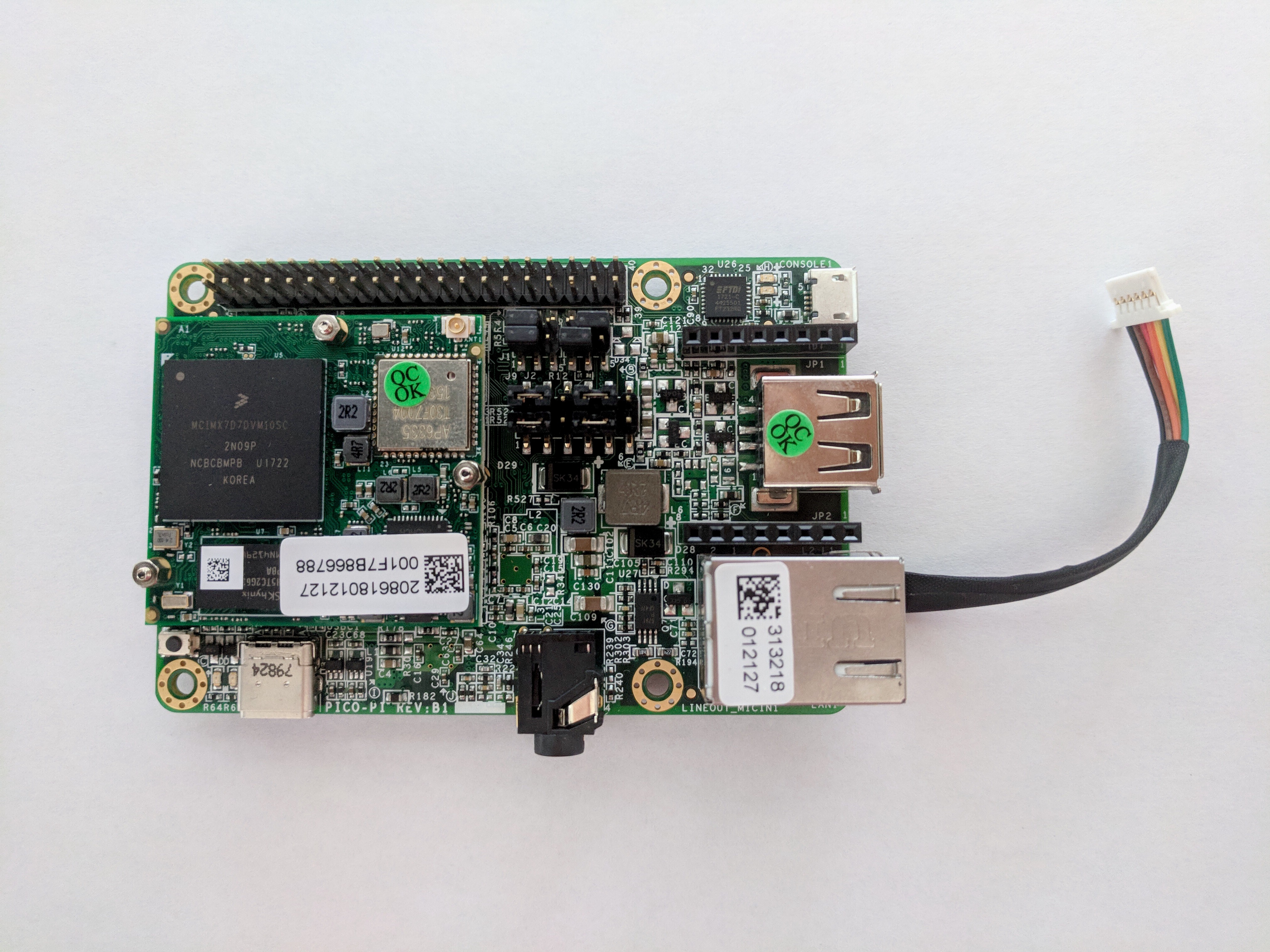
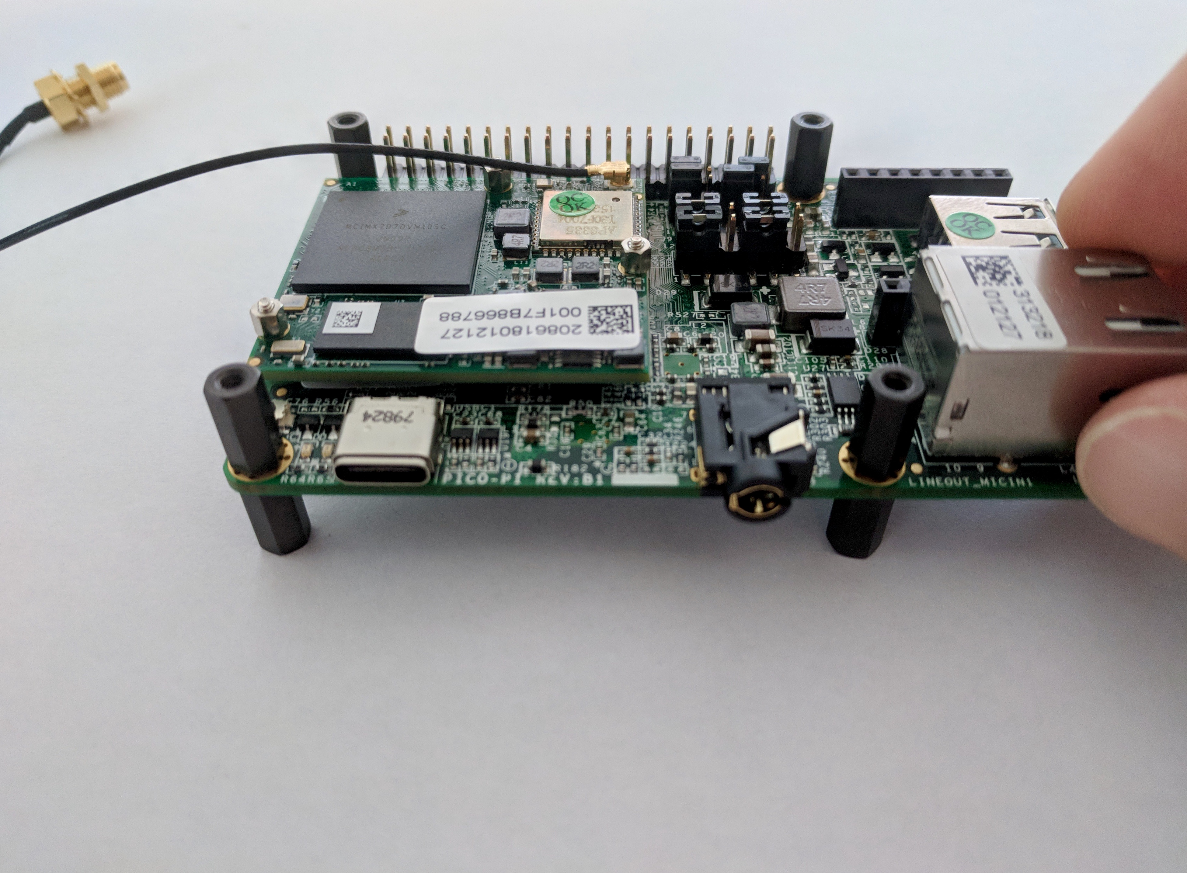
Start by finding your Pico i.MX7D Development Board and a clear workspace
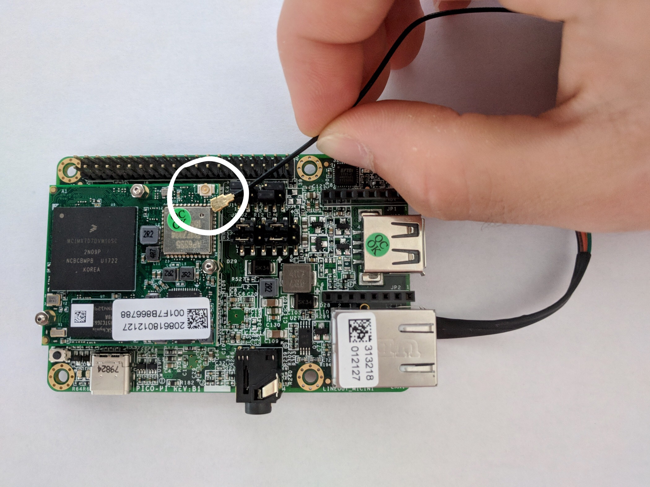
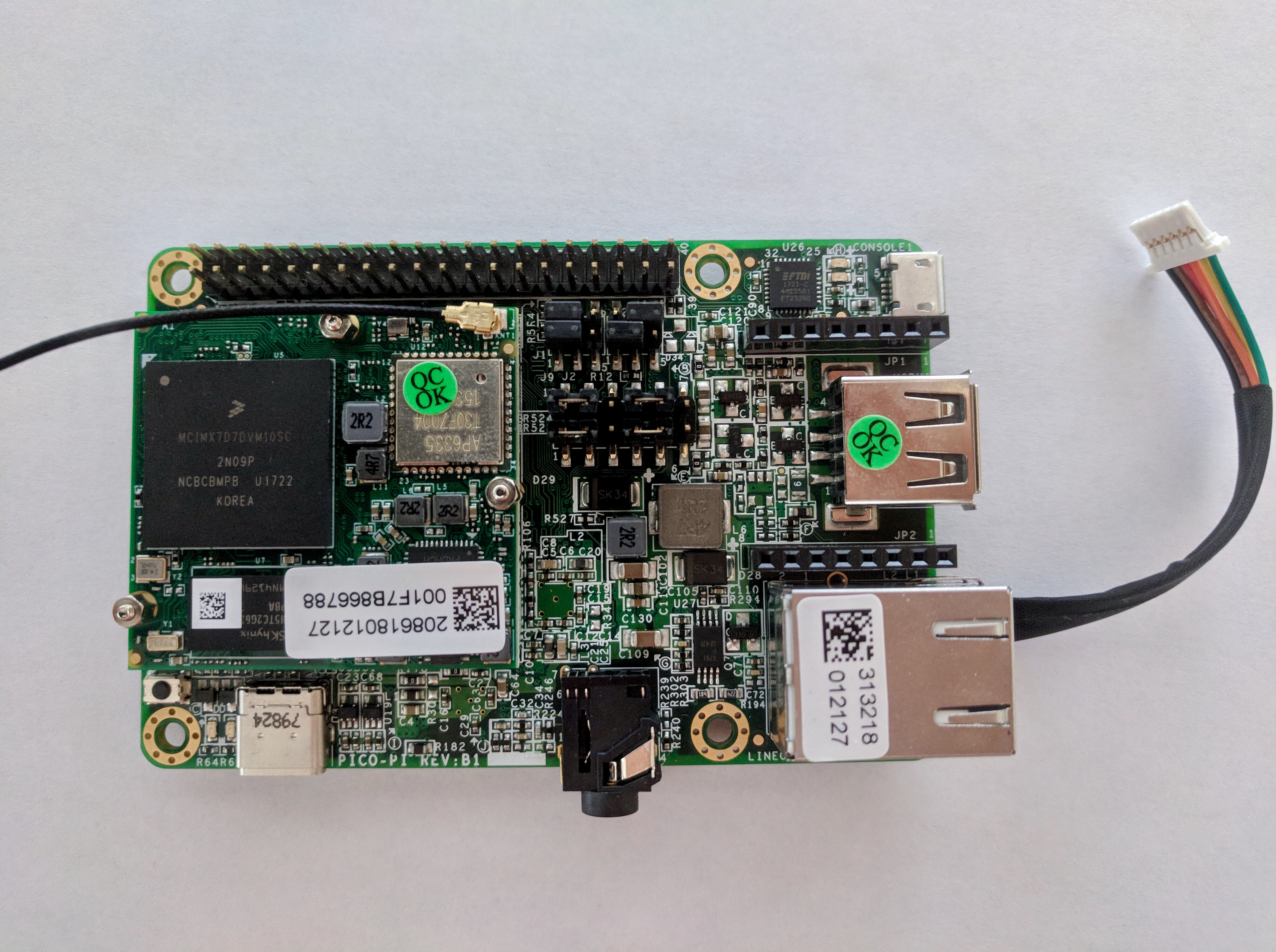
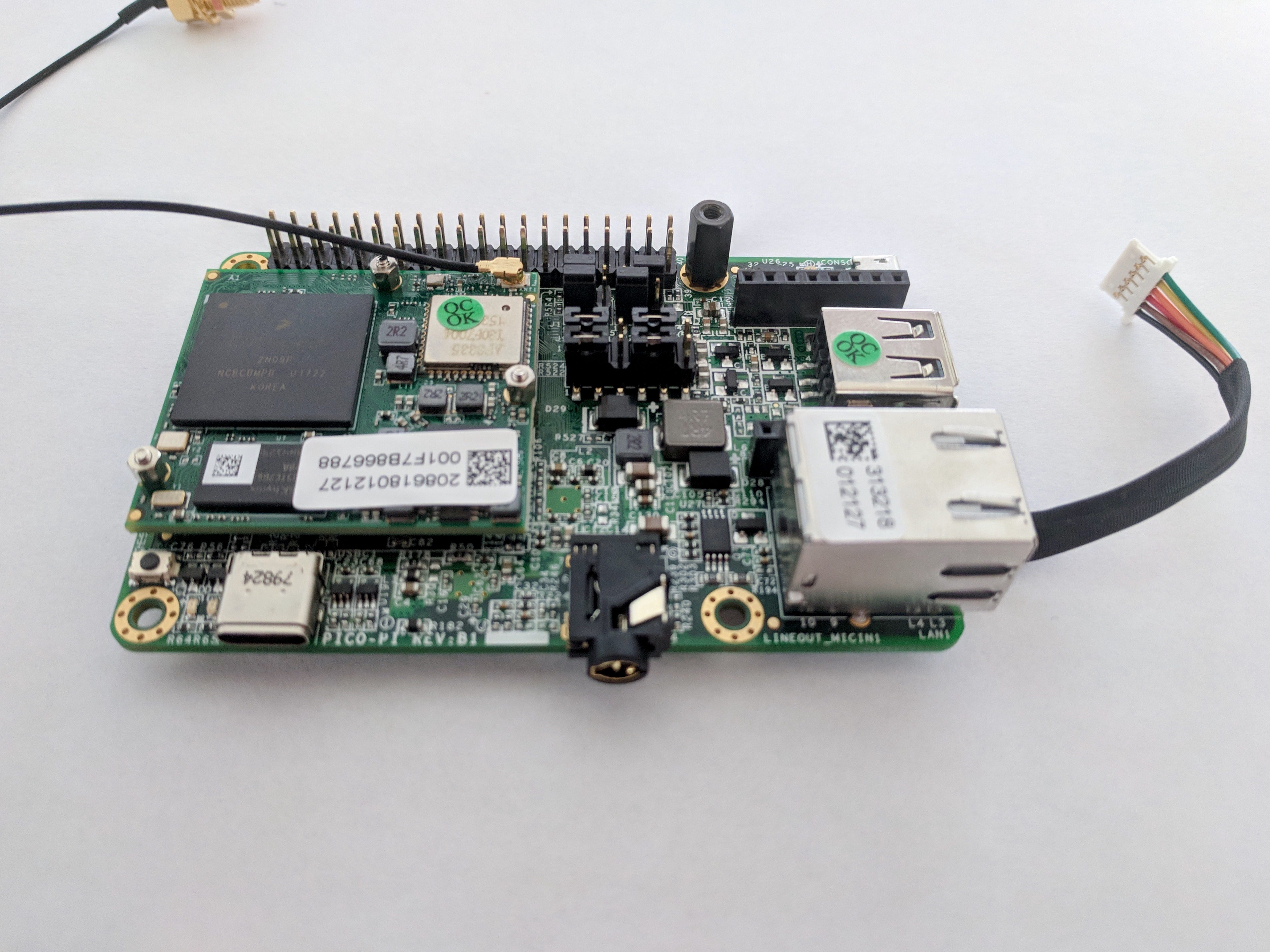
Start by finding your Wi-Fi cable, leave the antenna for now as it will only get in the way. Take the non-threaded end and press it onto the golden Wi-Fi port on the development board.
it takes a little force but once you have it, you'll feel it click into place and it should feel pretty secure. Now let it trail off to the left of the board as seen below.
Now take one of the regular screws found in the accessories box in the kit,
and put it through the back of the screw hole to the right 40 pin layout on the Development board, so that the threads come out on the same side as the pins.
Now secure a standoff to the screw as seen below.
To double check that you put it in the right place, it should look like this currently.
For the other three screw holes, take the three standoff with a screw end and put them through the back so the screw portion is facing the same was as the screw from the previous step
Top them all off with standoffs, so that it looks like this.
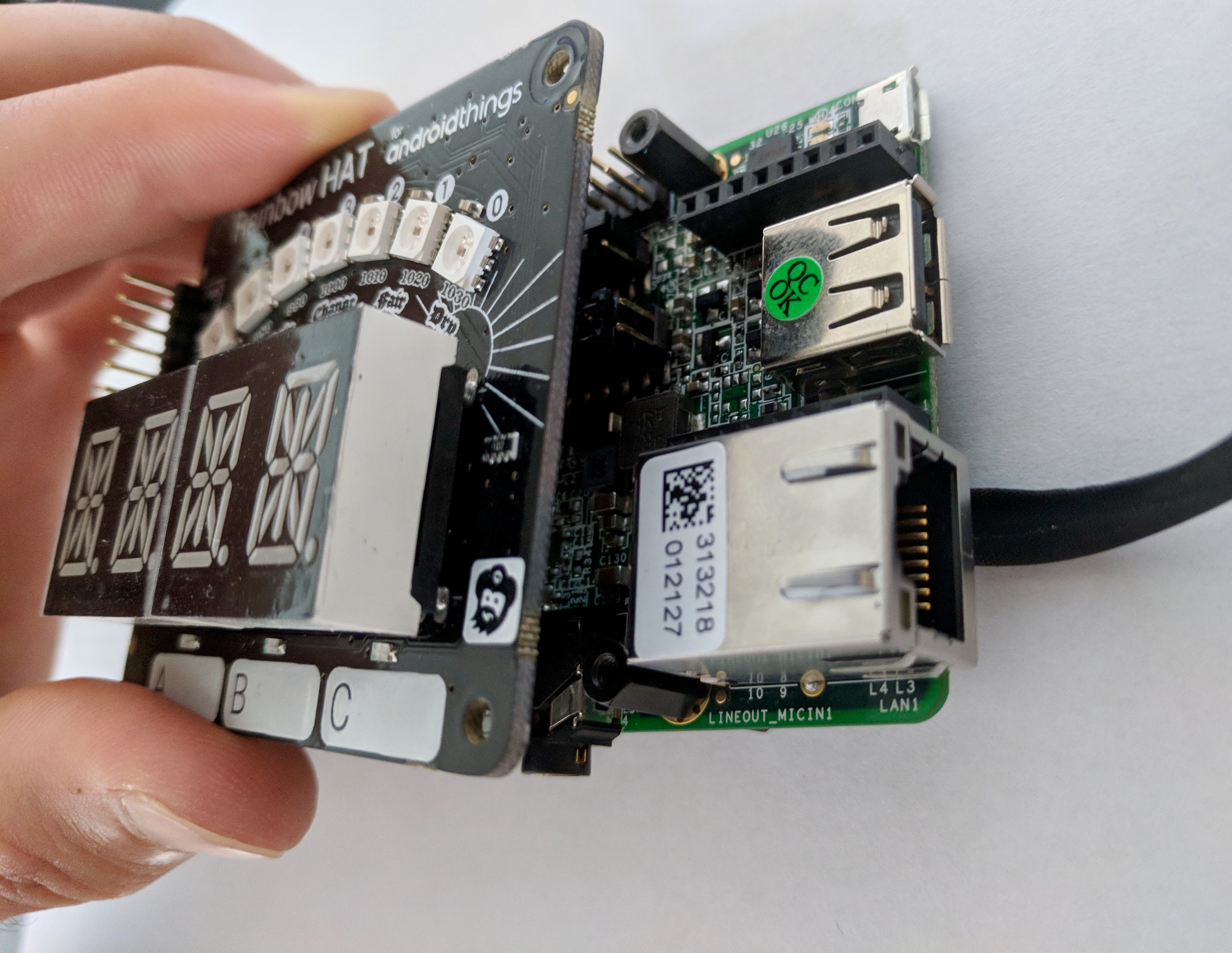
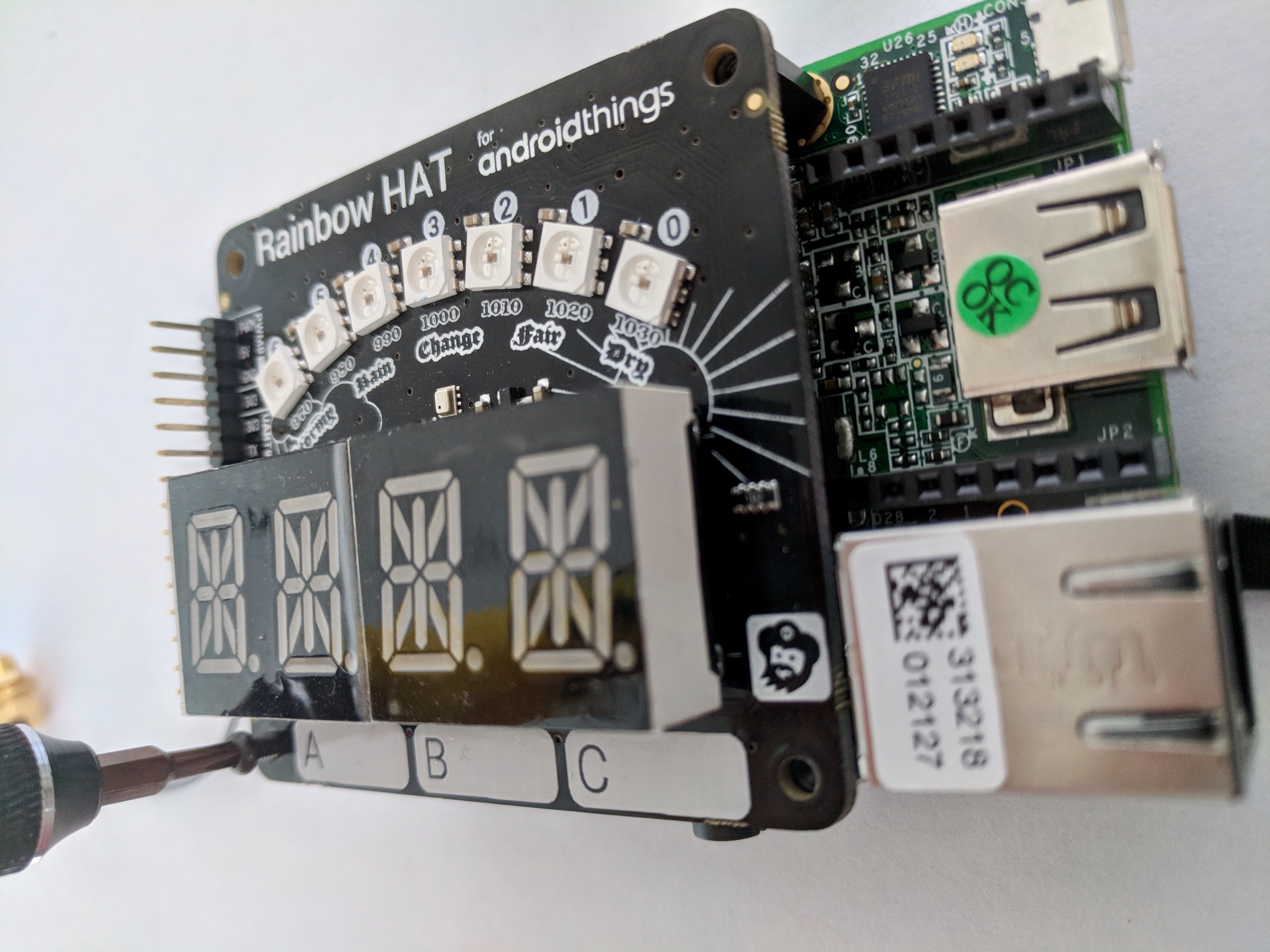
Now lets install the Rainbow HAT. Line up the 40 pins of the Development board with the 40 pin breadboard portion on the rear of the HAT, like this.
Double check that the pins are lined up and press firmly until the connection is secure, and then continue until the mounting holes are flush with the standoffs on the development board.
Then secure the HAT by using 4 screws and securing them the standoffs.
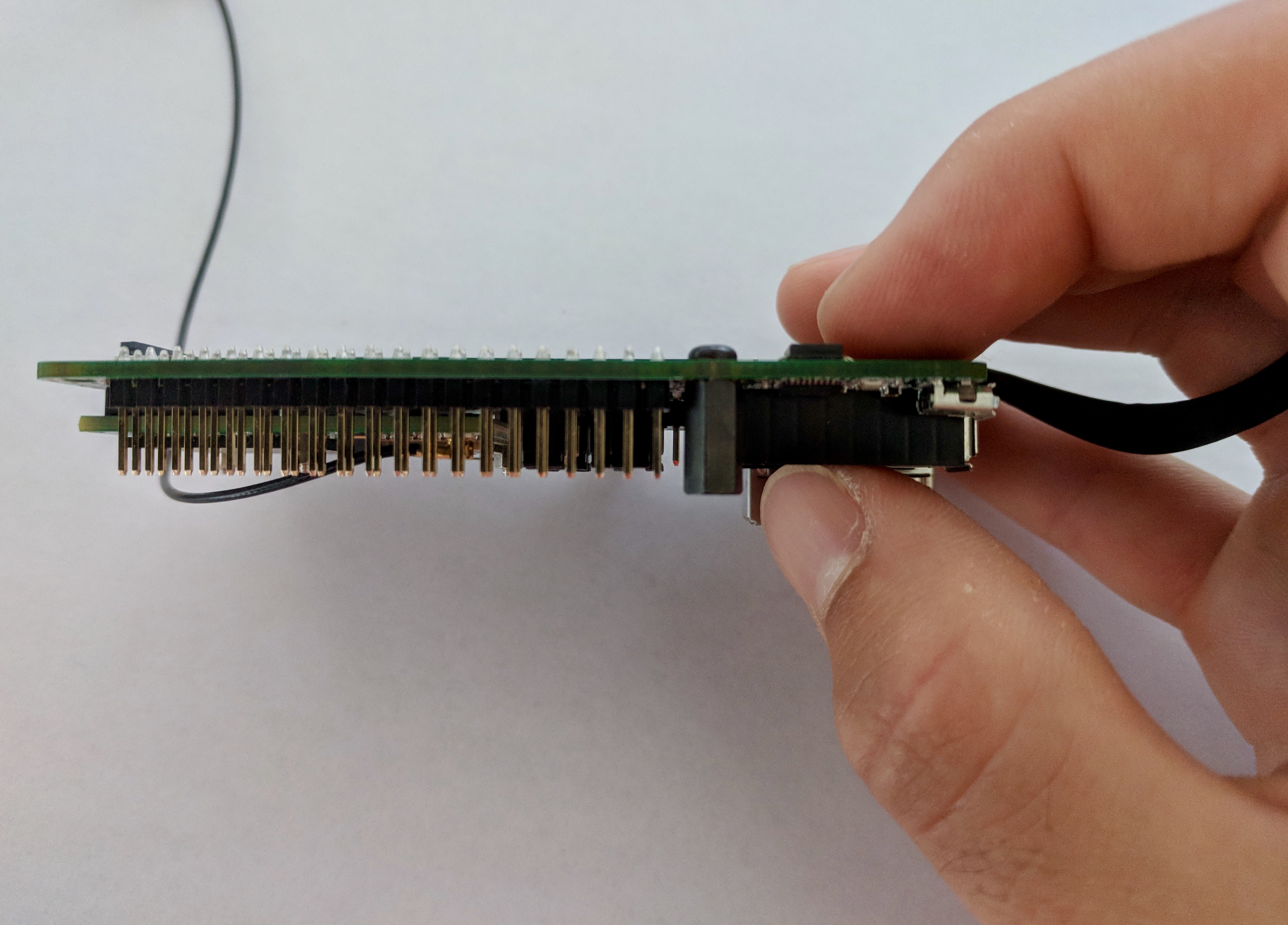
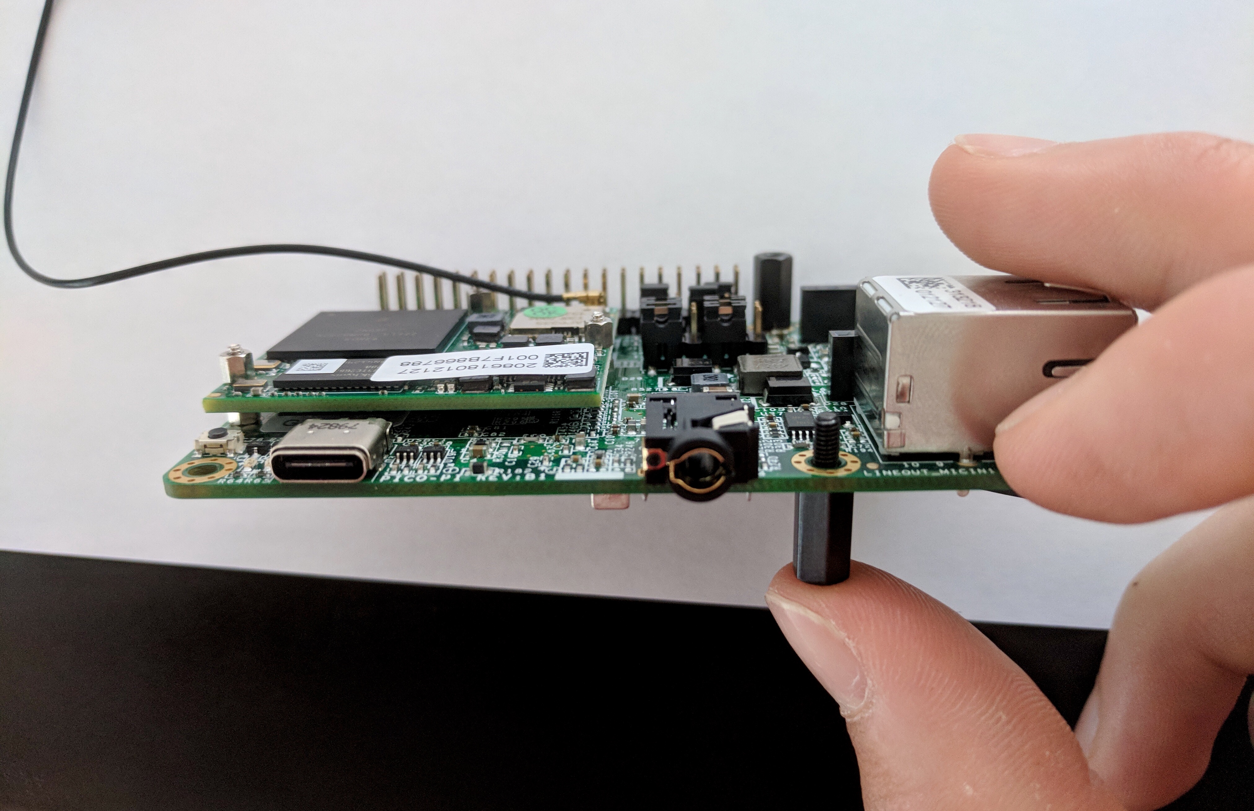
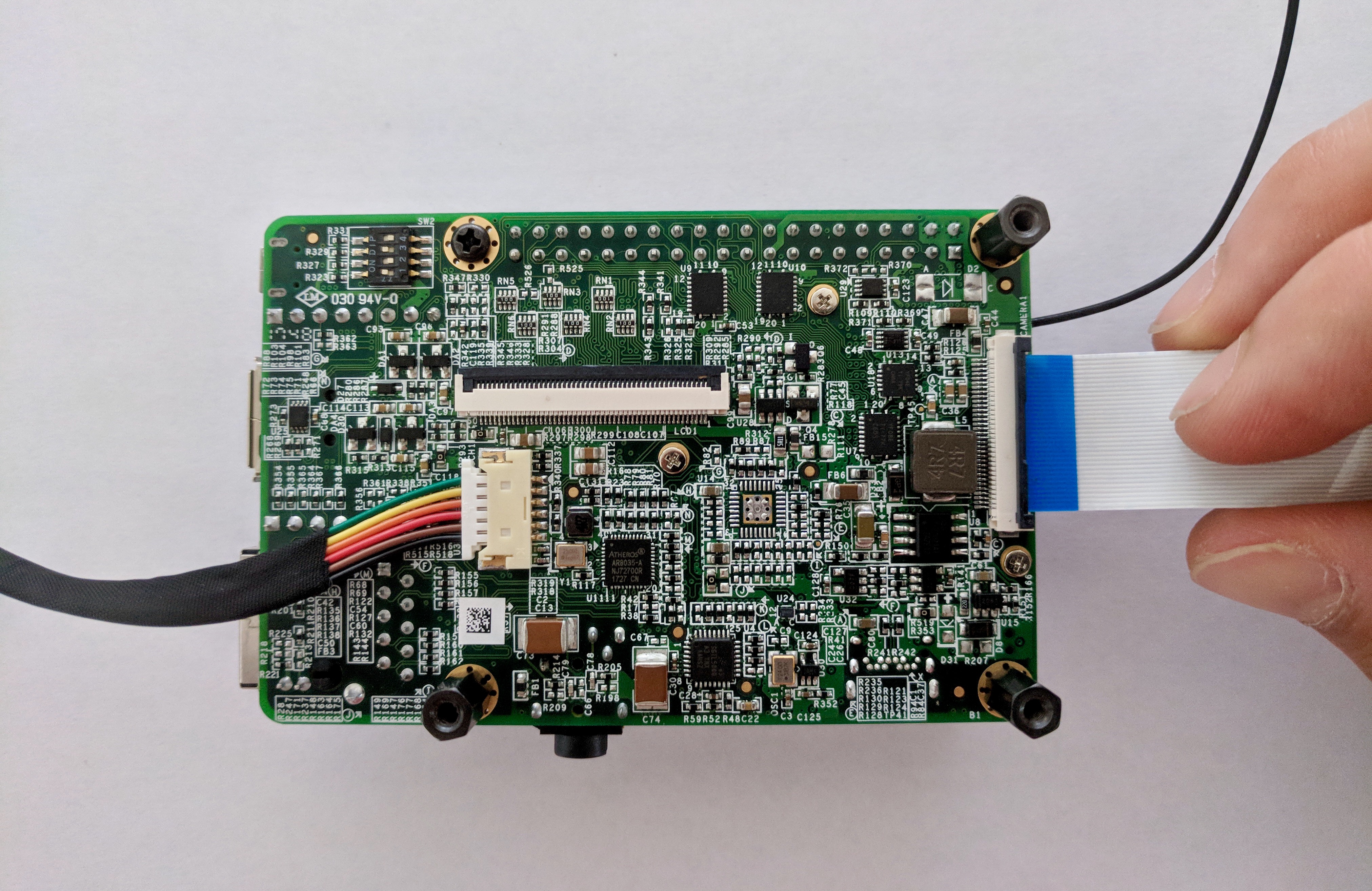
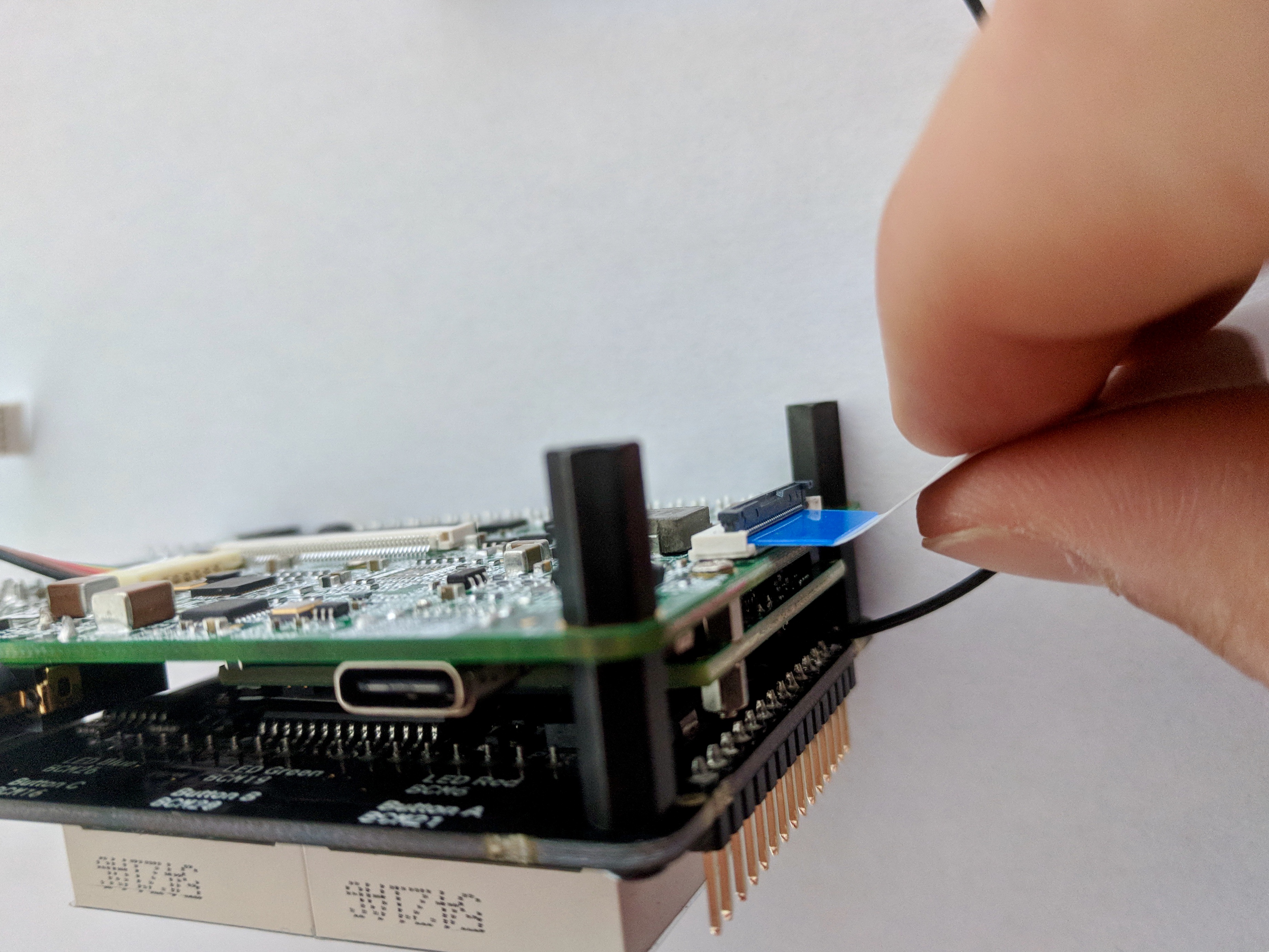
Once you've installed the HAT, flip over your development board and locate the camera port. It has a 'camera1' label to the right of it.
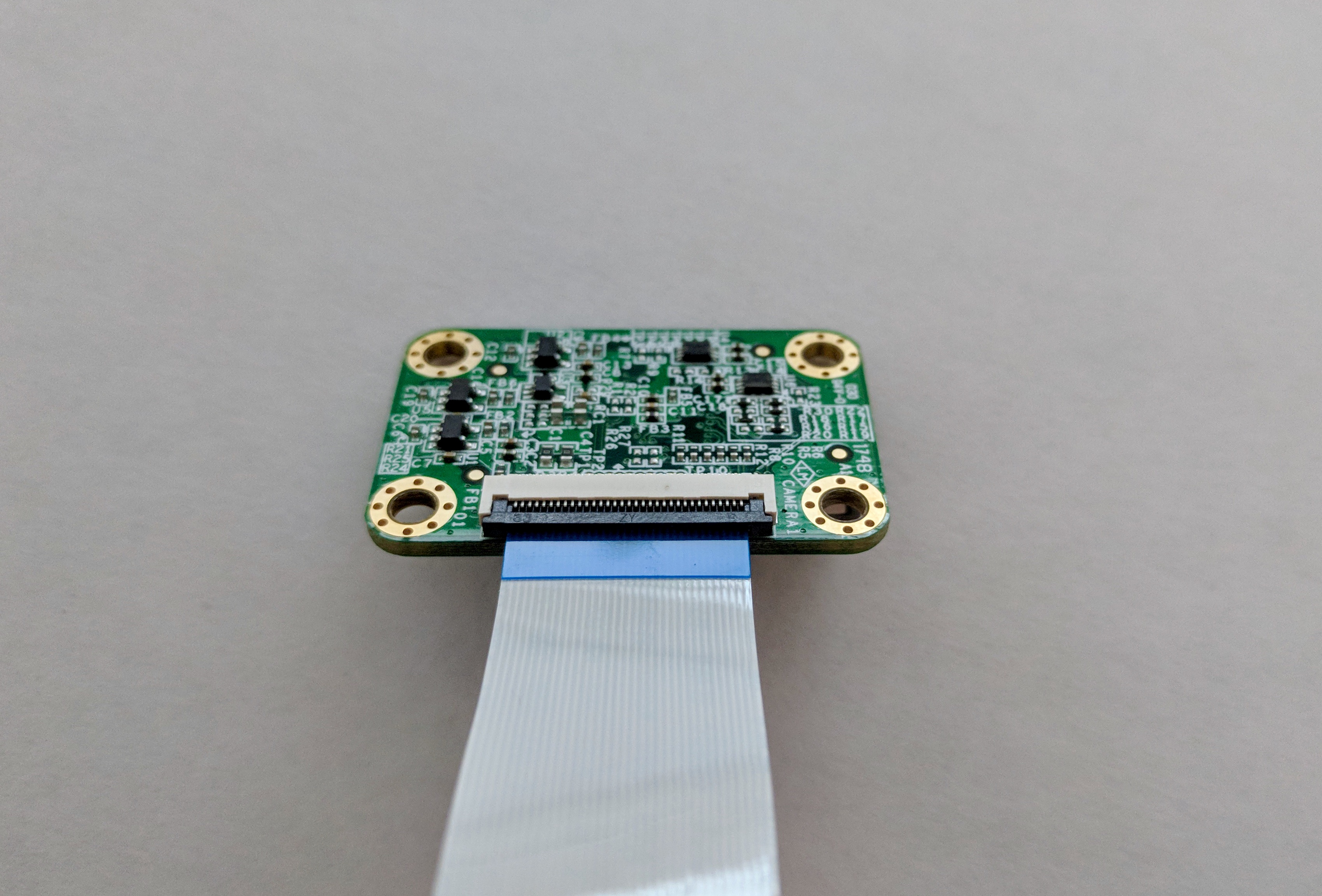
Once you've found it flip up the little black latch and find the ribbon cable provided in the accessories box.
Once you've opened the latch put the ribbon cable in pin-side down (blue side up as shown in the photos), as shown below:
and close the latch so it looks like this:
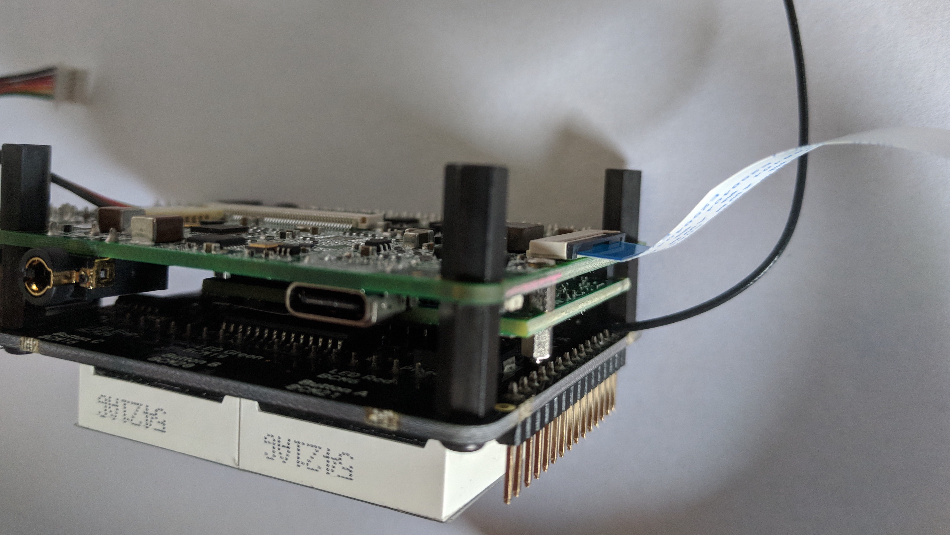
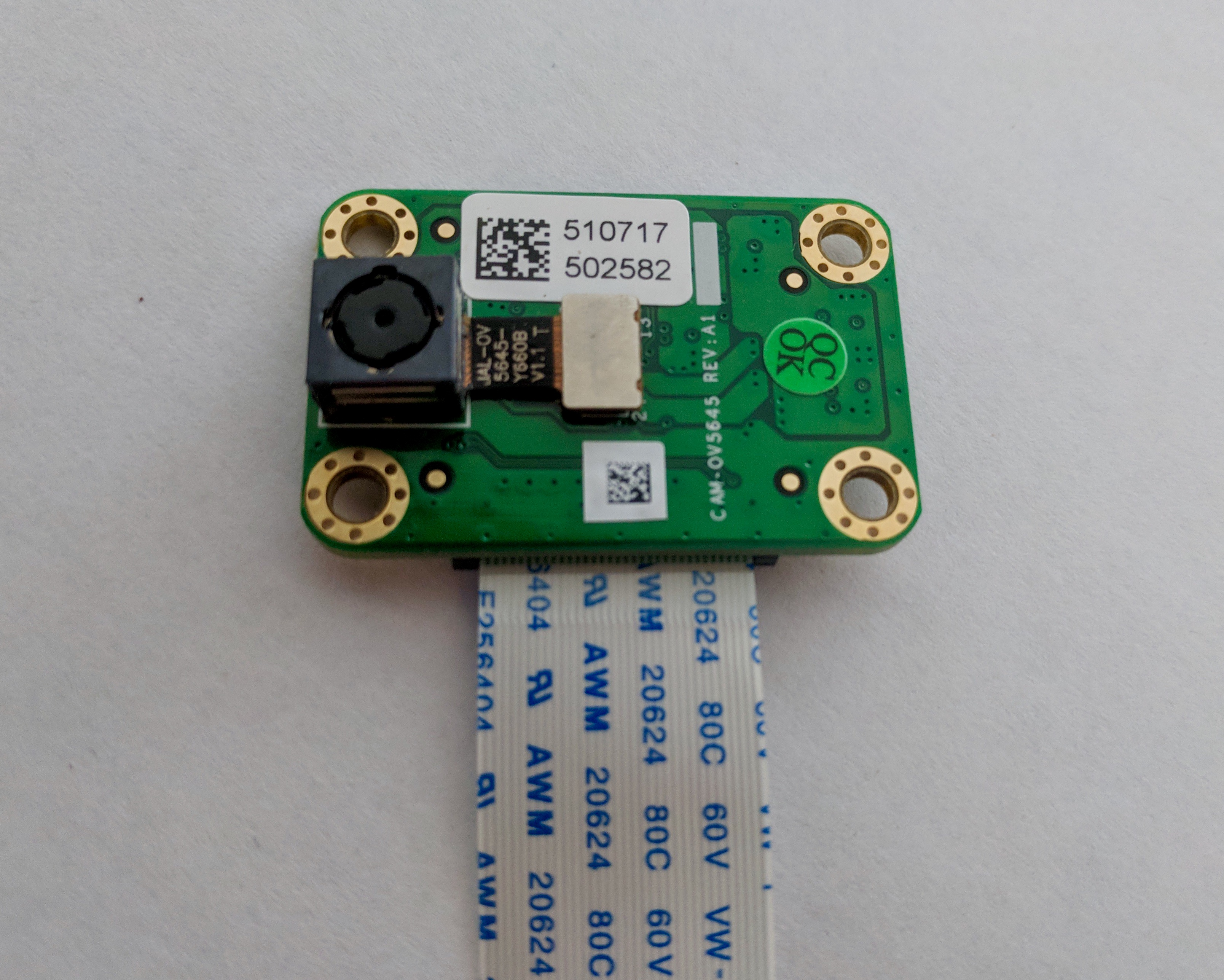
Now repeat the same procedure on the actual camera module.
Again pin side down, so blue side up. Once installed it should look something like this.
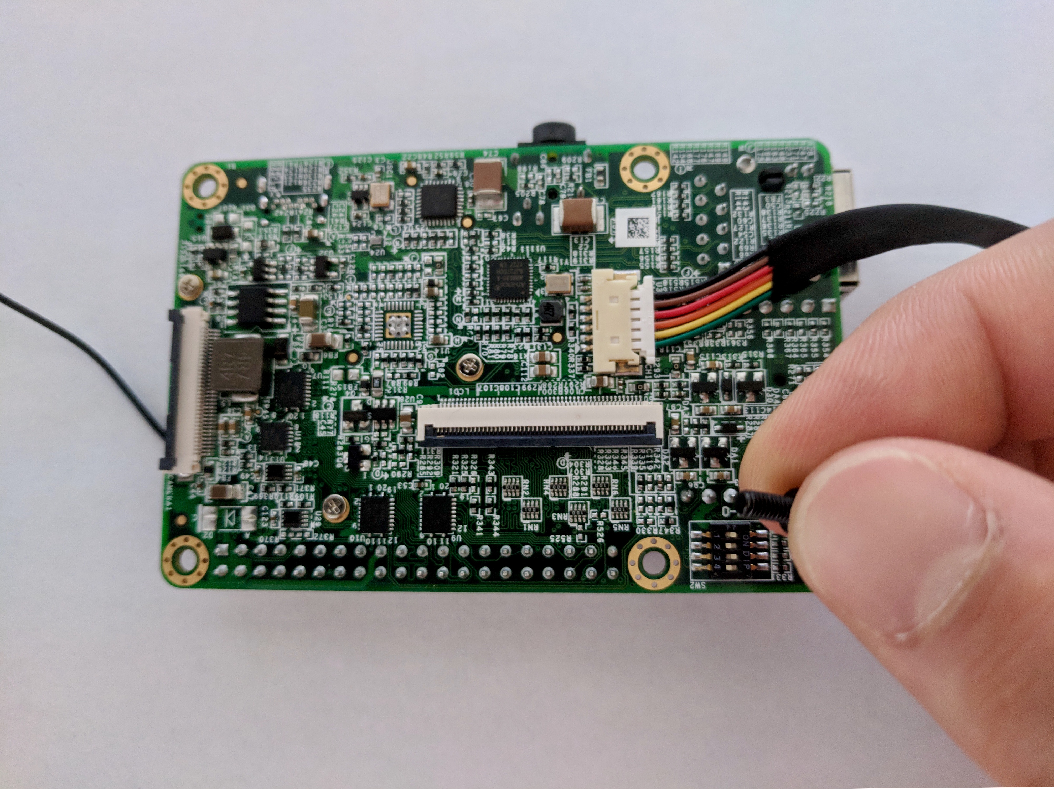
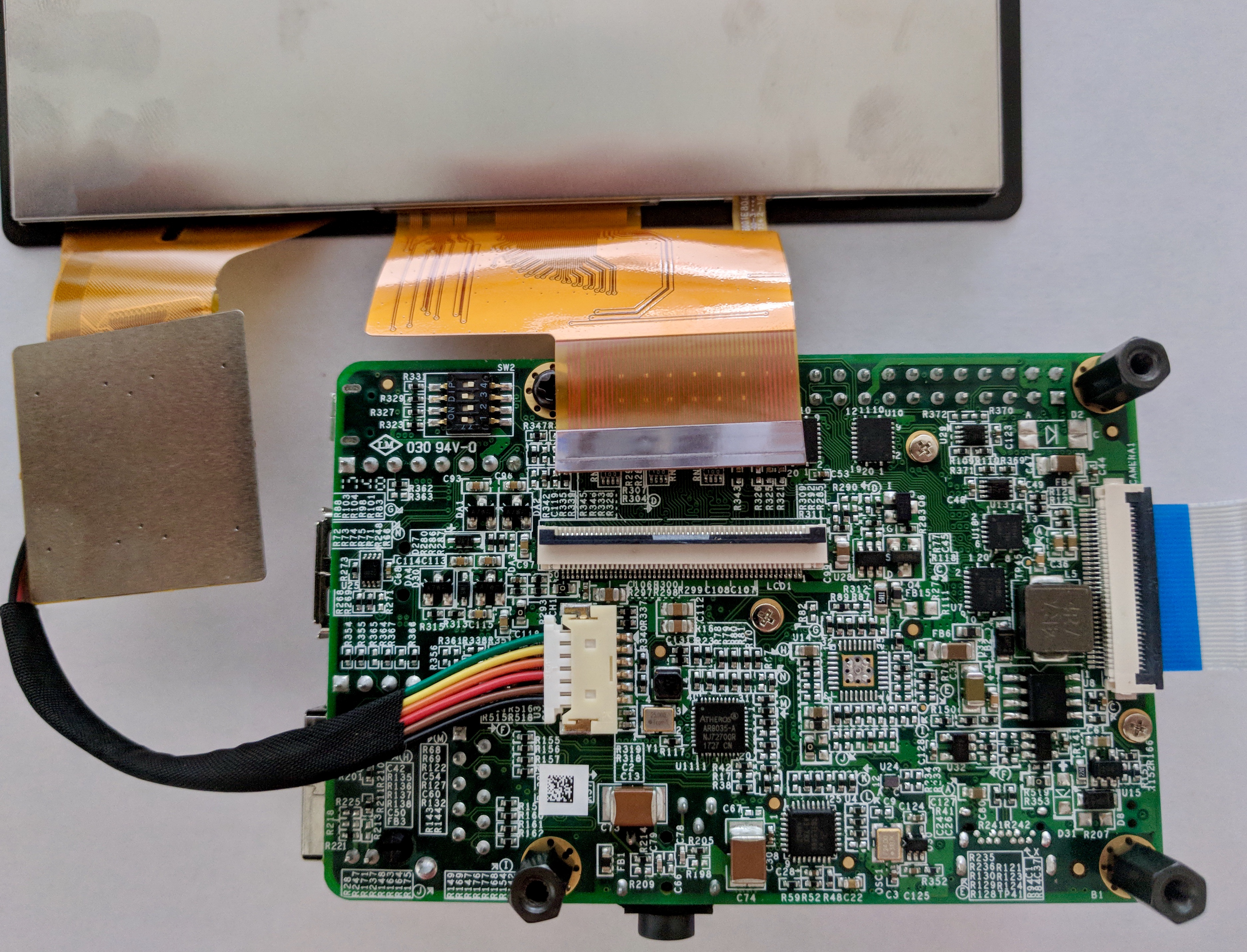
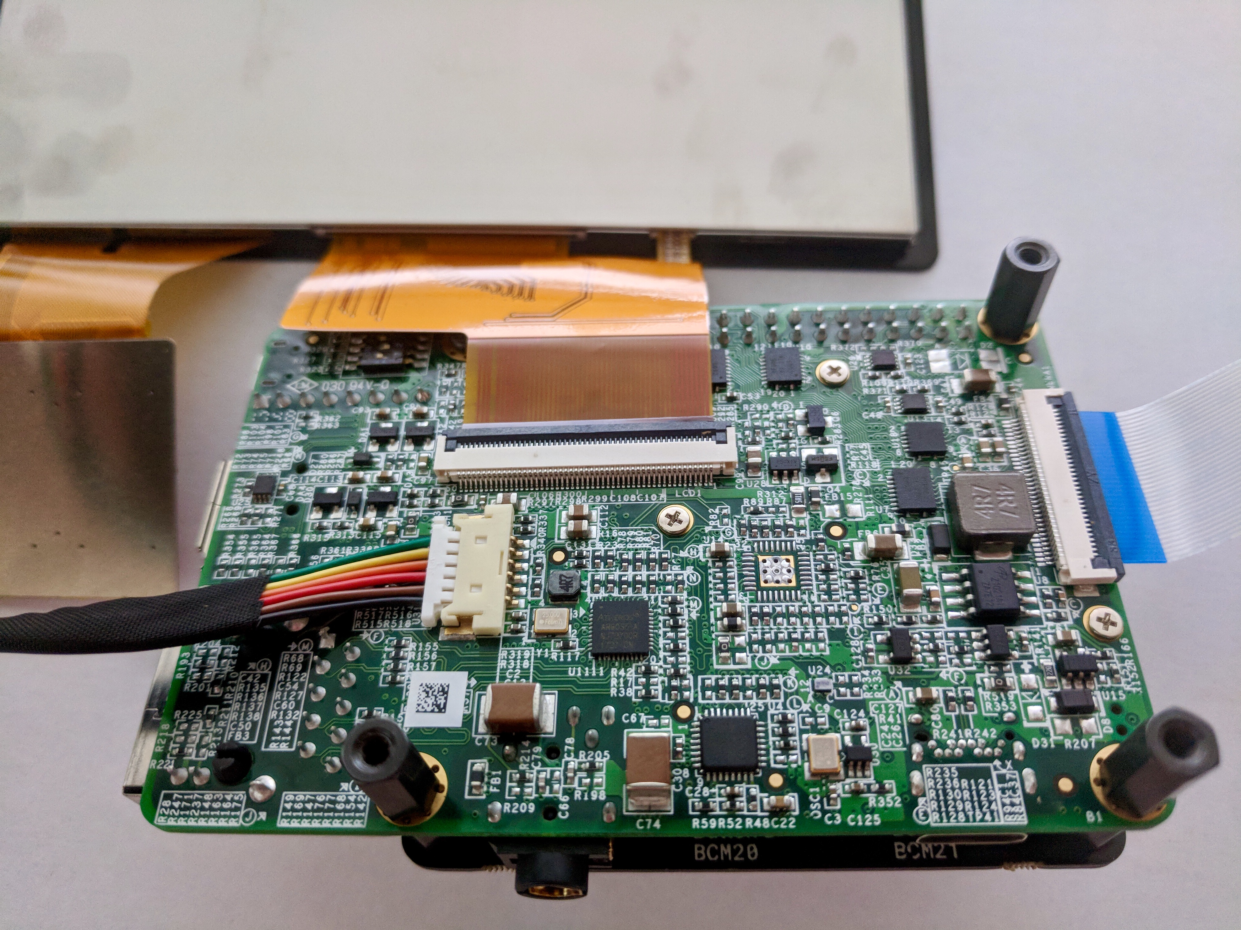
Now to install the display, keep the board flipped HAT side down. The display port is labeled 'LCD1' and is the only other ribbon cable port on the development board. As you did for the camera, open the latch on the development board port and slide the display cable in pin side down (silver side up).
Close the latch and voila you're done installing all the components.
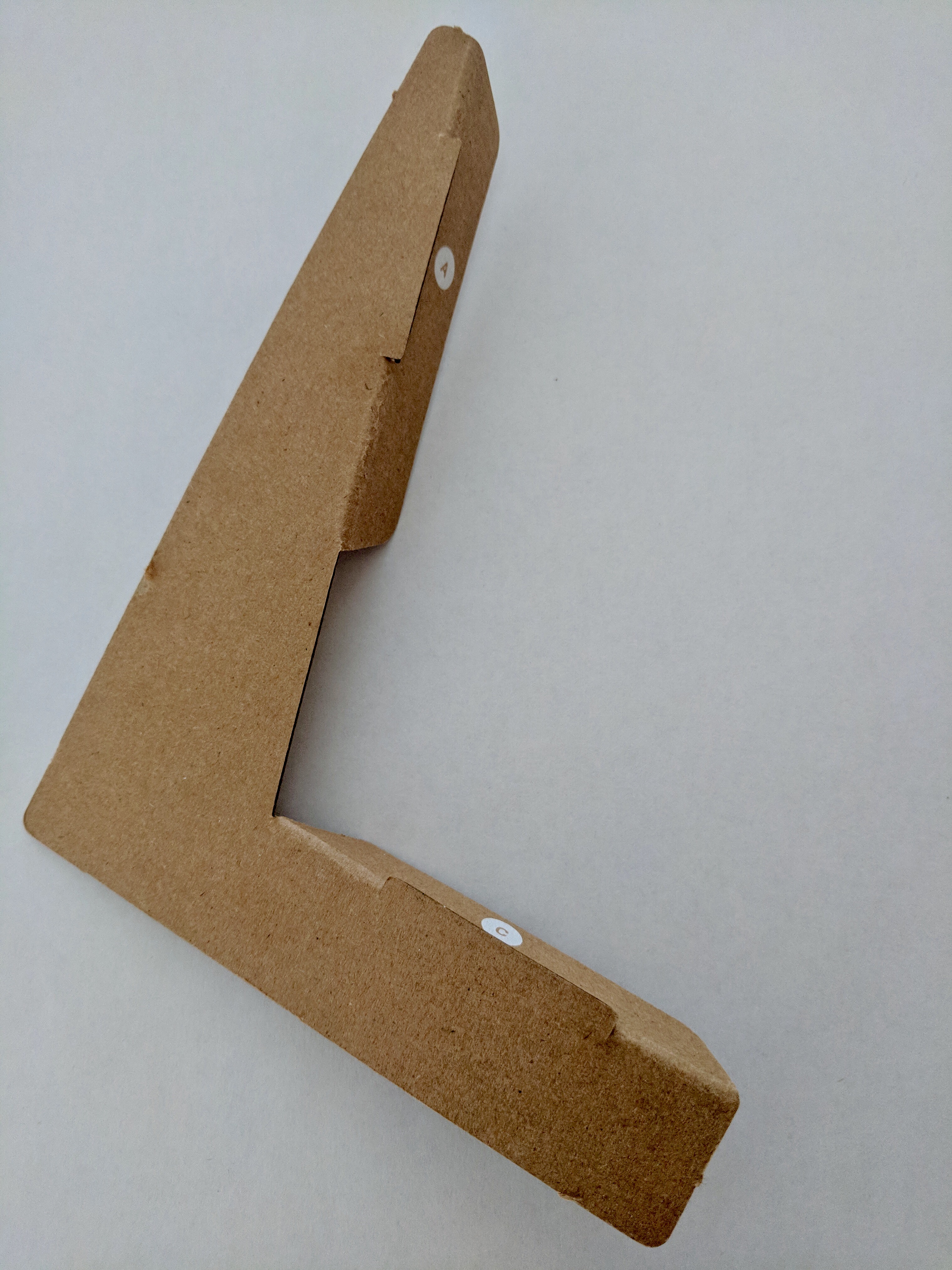
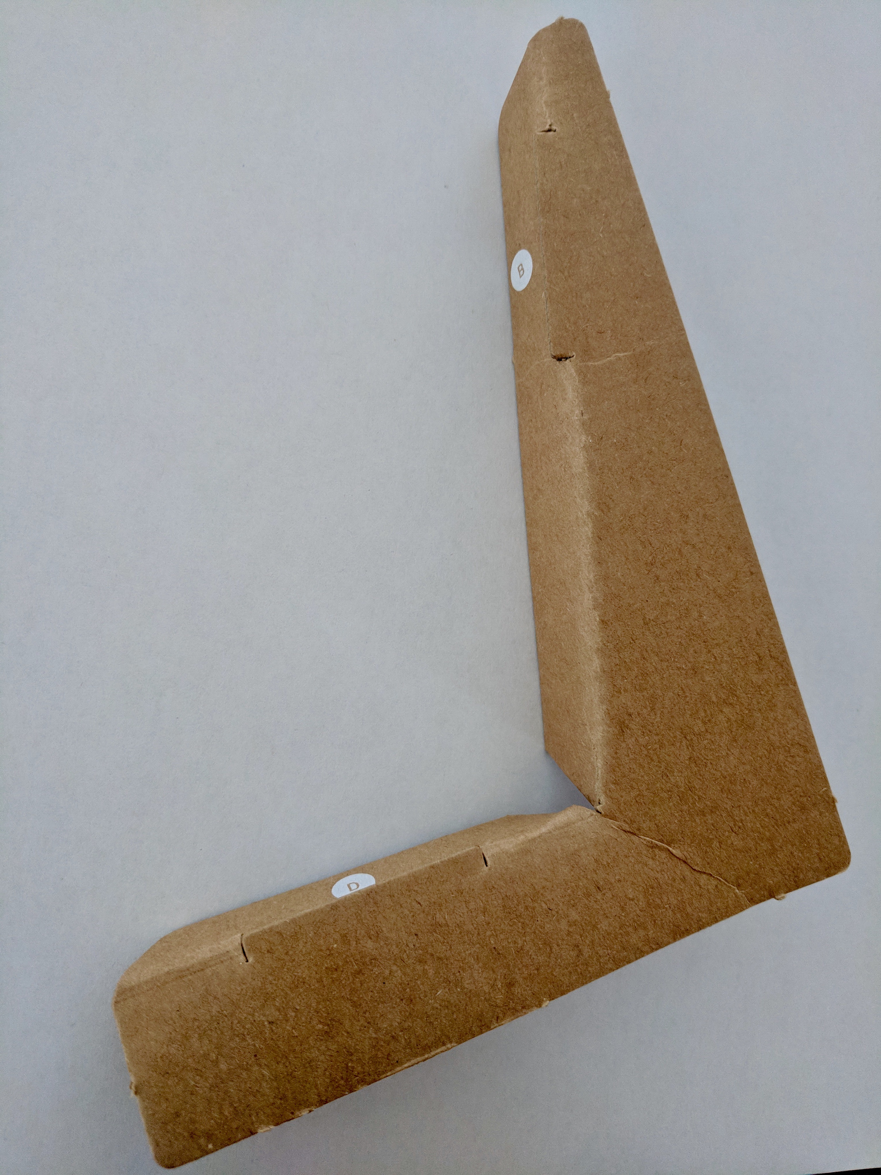
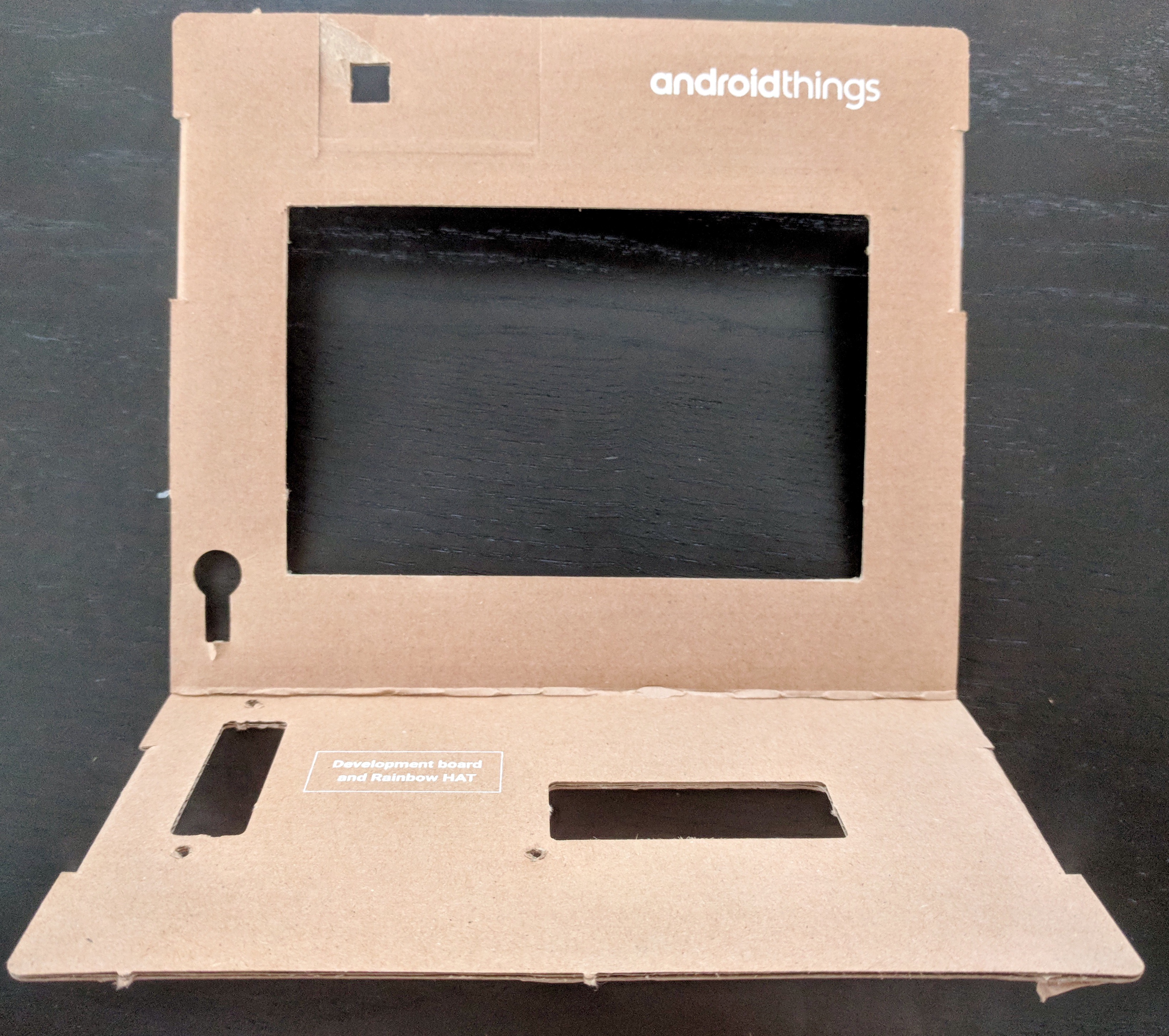
Now separate all the cardboard cut outs. Lets start with the two leg pieces and fold down the lettered tabs to a 90 degree angle like so:
Repeat for the other side.
Now fold the lettered tabs of the center piece also to a 90 degree angle, and fold it along its horizontal indent to around 70 degrees.
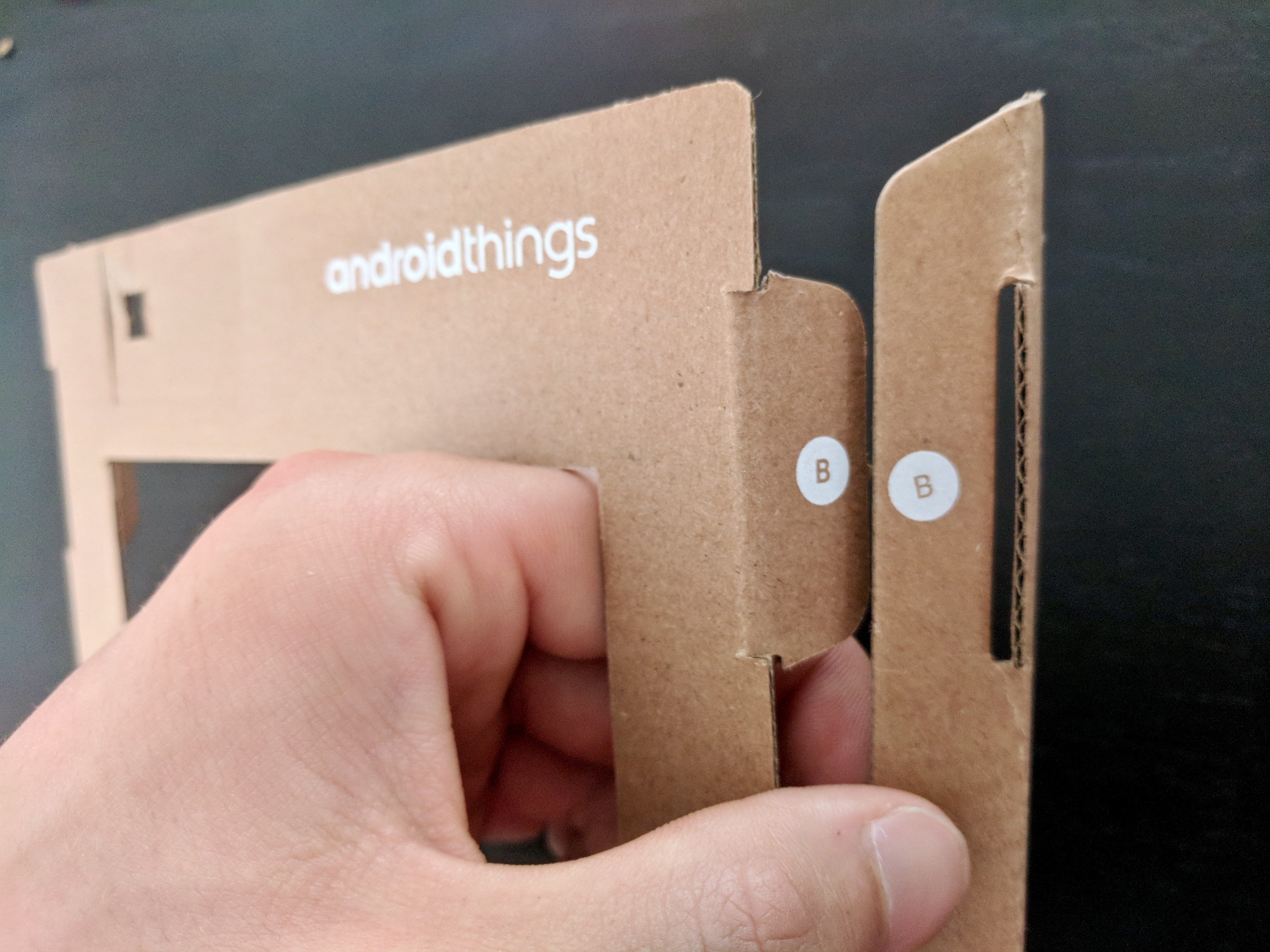
To connect the legs of the stand match up the lettered tabs of the legs to the lettered tabs of the body and put the tabs through the cut outs.
Once inserted it should look like this:
Now repeat for the other leg.
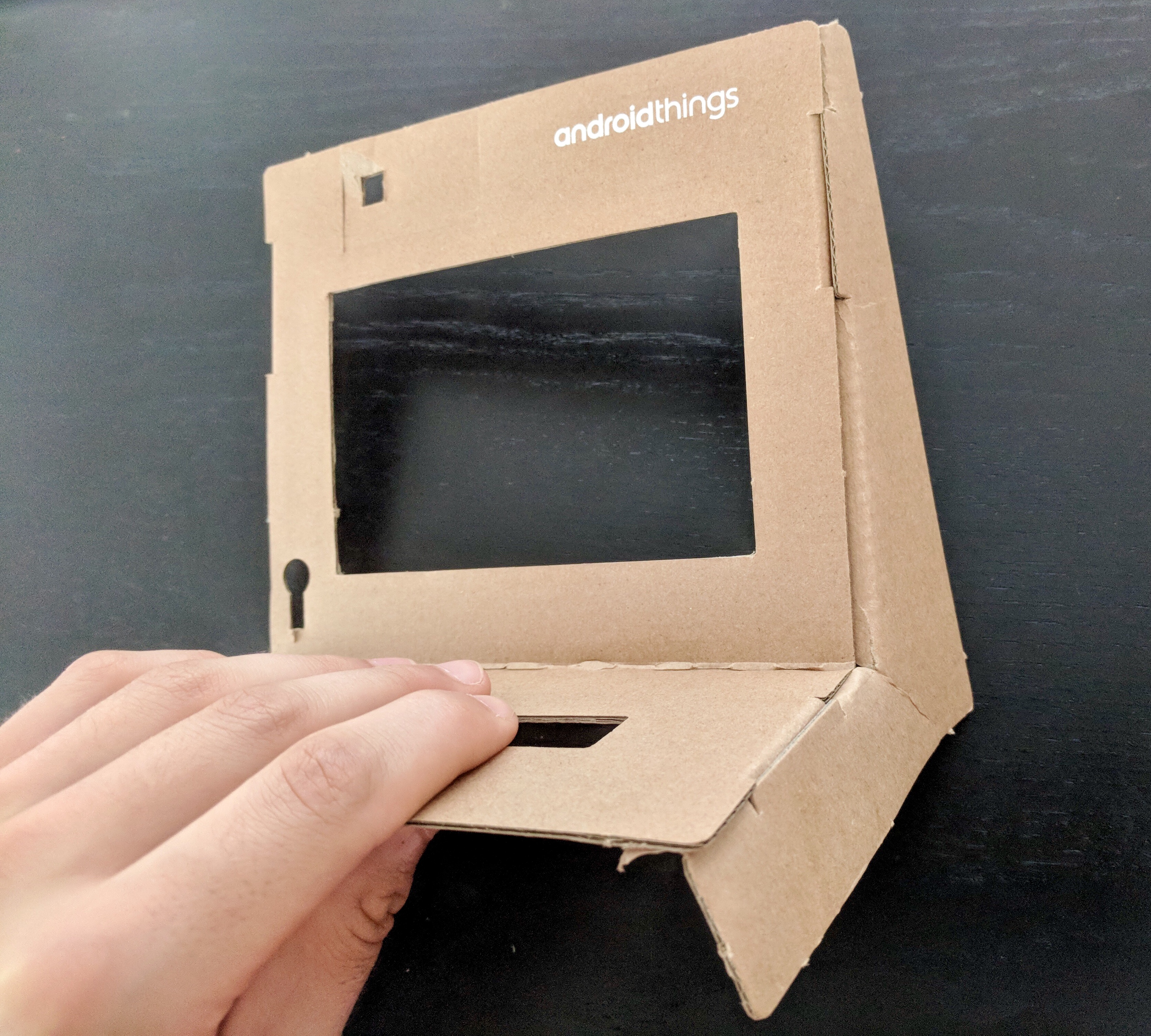
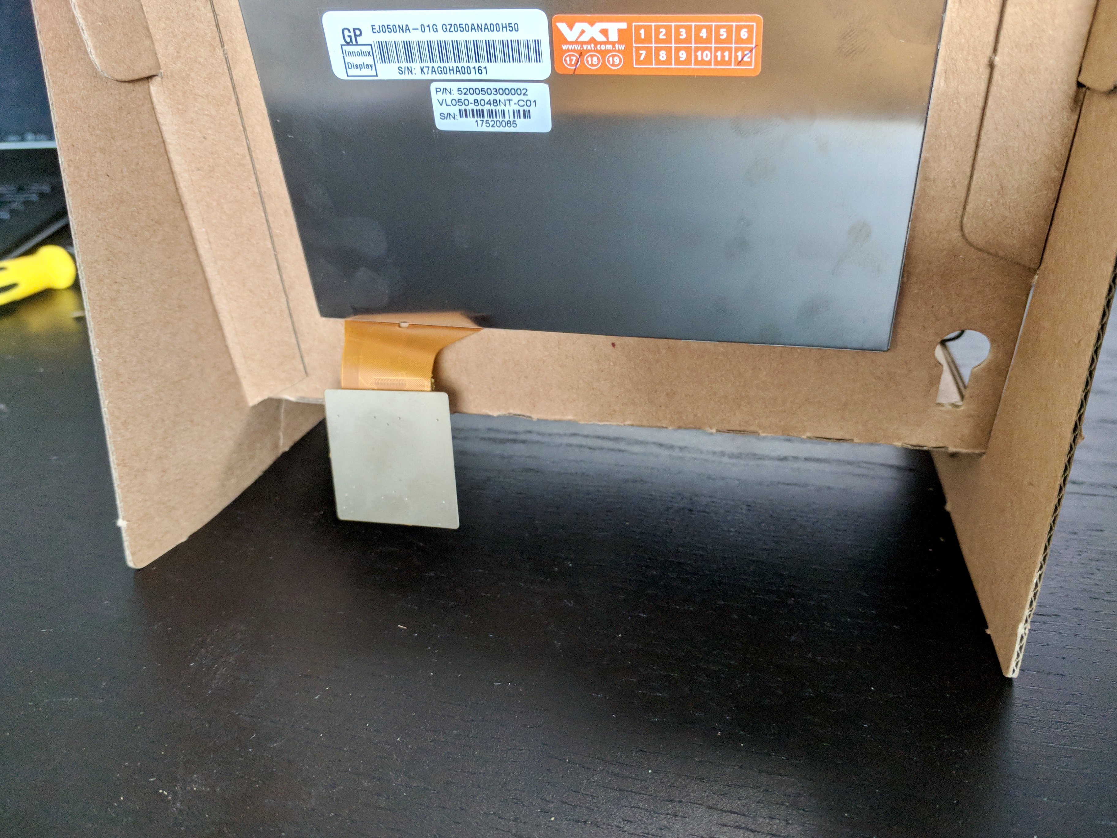
Once you've completed the cardboard frame it's time to start installing the Development board. Start by pressing the back of the display through the big screen cut out until the bezel is flush with the front of the cardboard. Make sure the cable out the back of the display that isn't connected directly to the Development board hangs out the back.
Make sure the cable out the back of the display that isn't connected directly to the Development board hangs out the back.
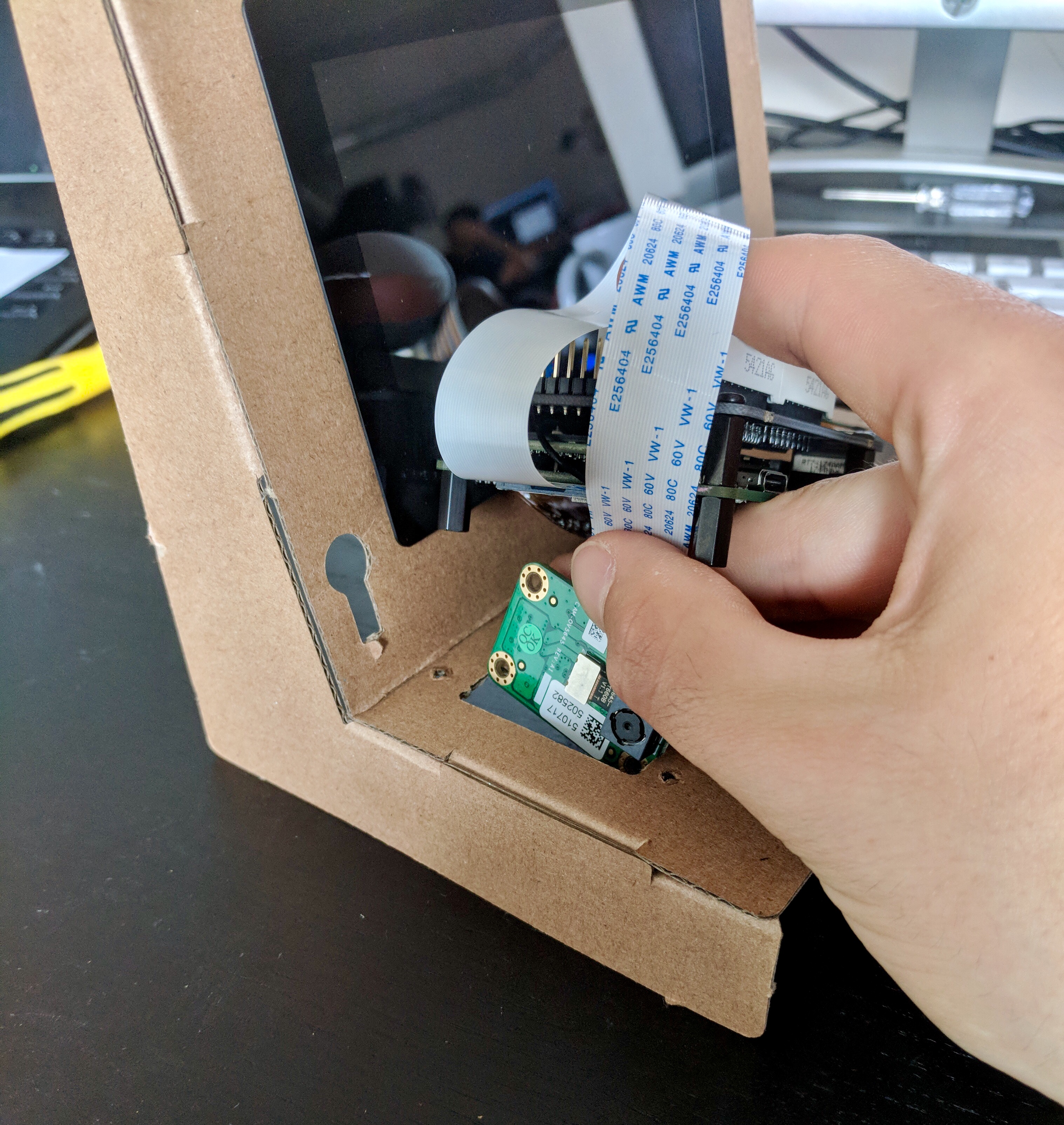
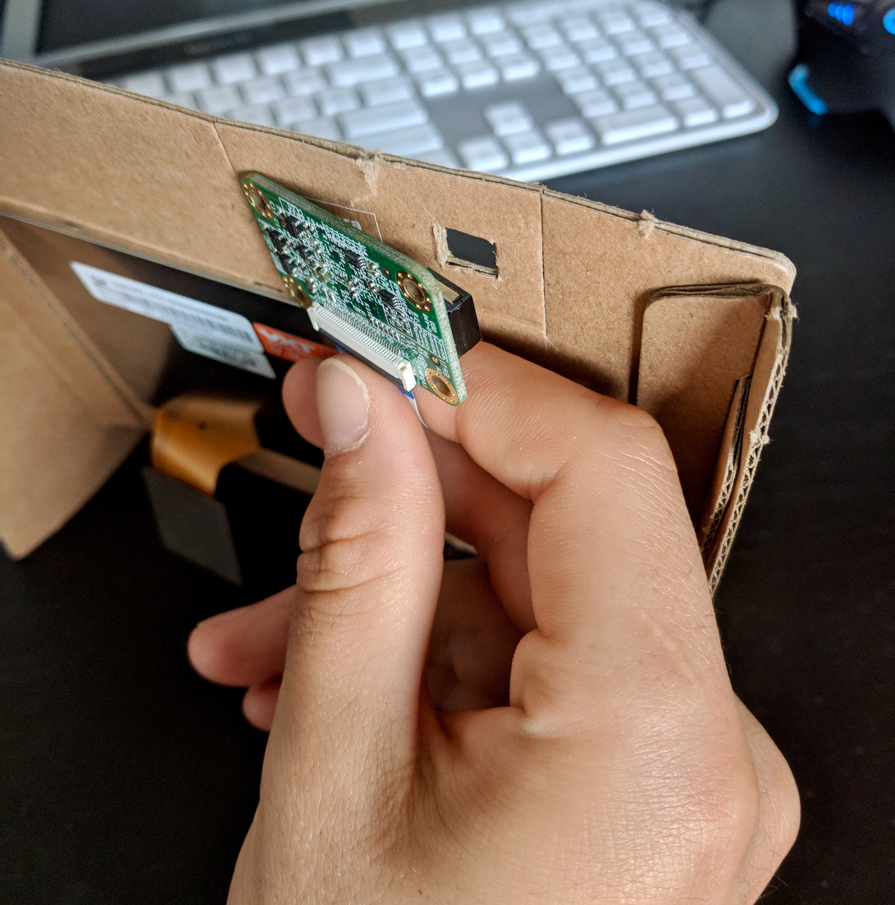
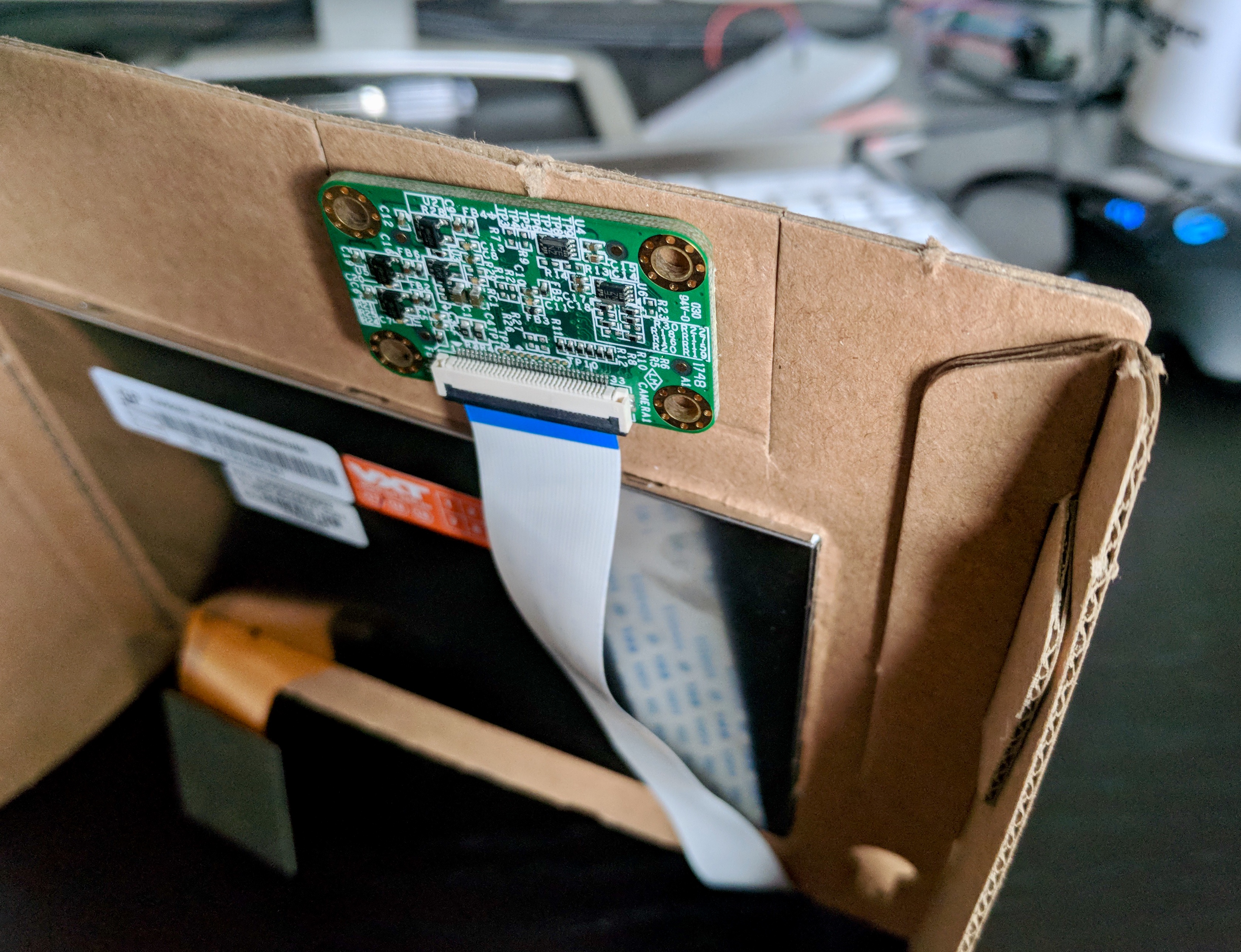
Once the screen is secured, put the camera module through the whole below its port on the Dev board.
Wrap it around, up to the top and press the lens through the webcam cut out in the cardboard.
Push until the PCB is flush with the back of the cardboard.
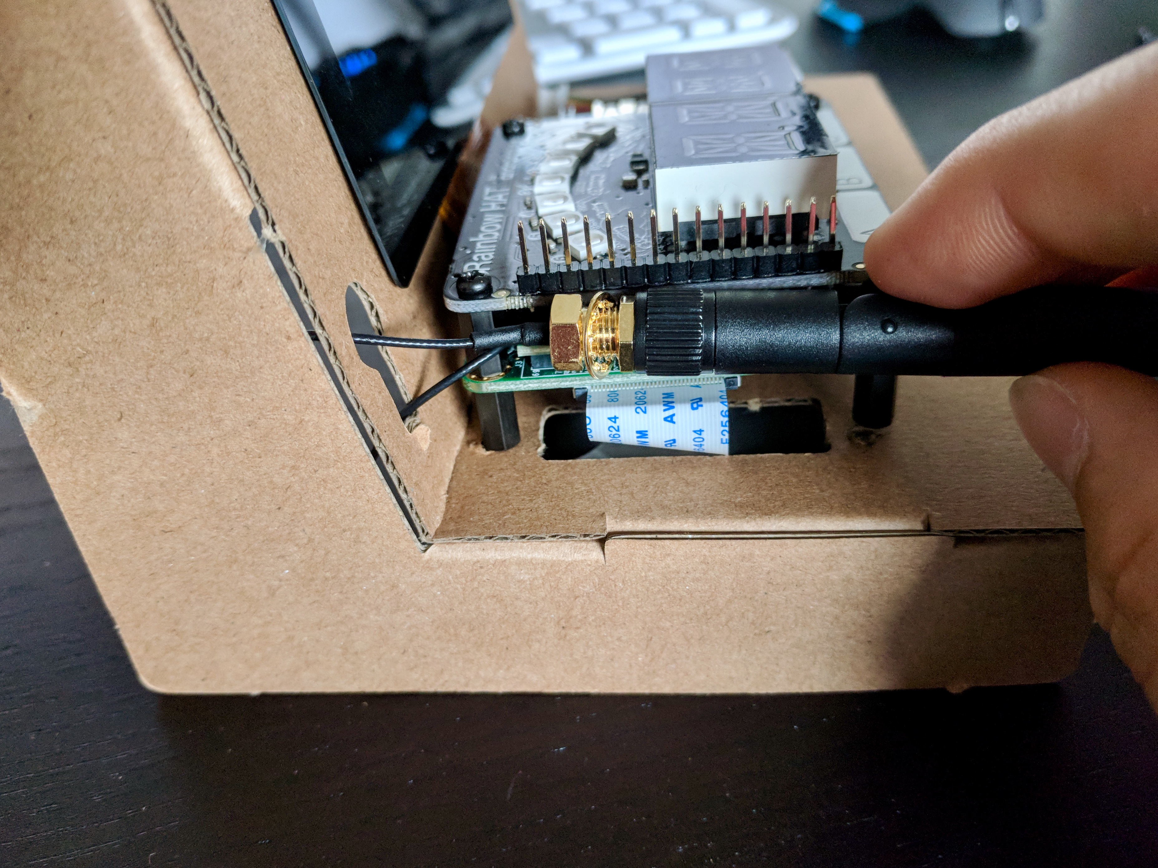
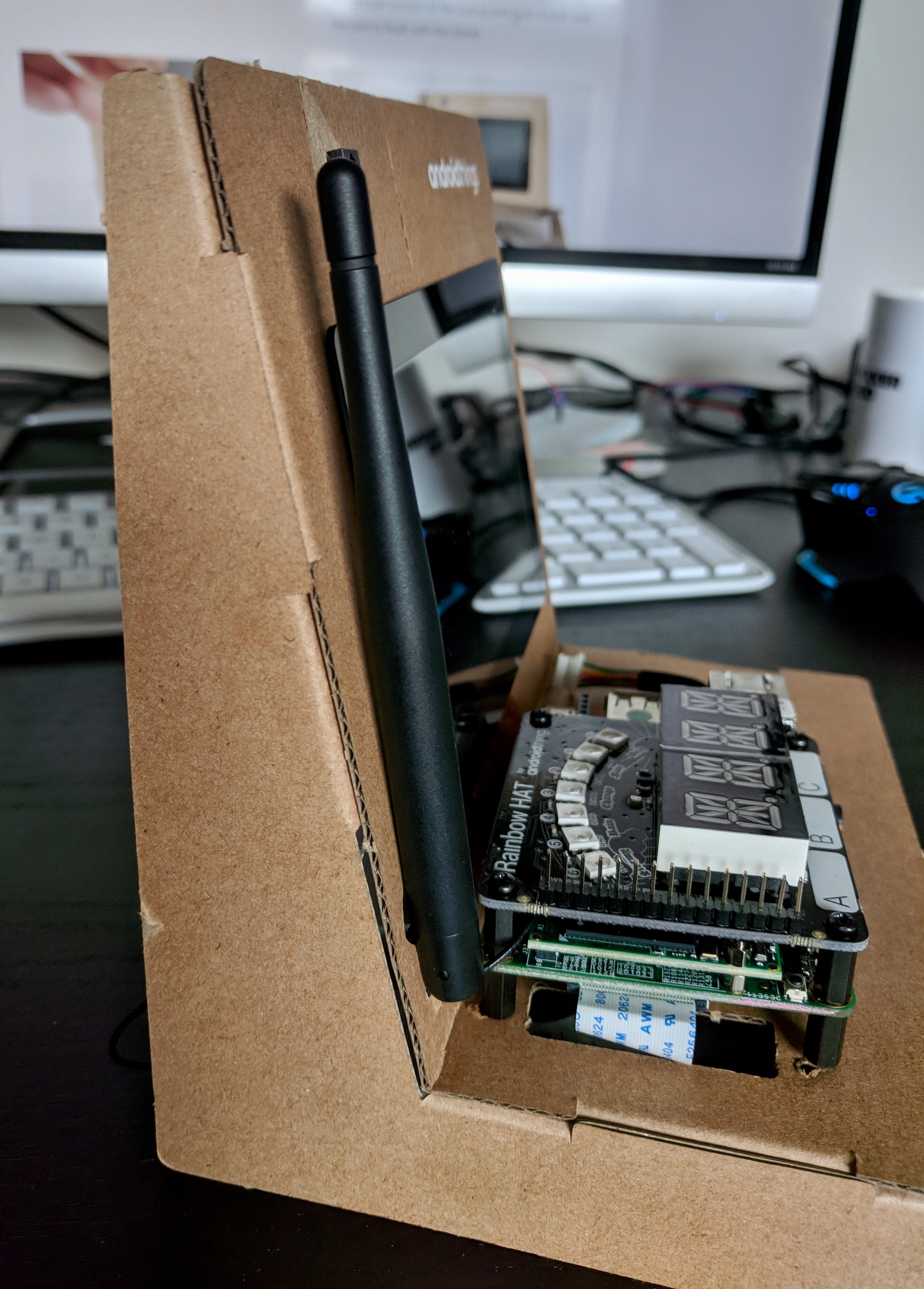
Next screw the Wi-Fi antenna onto the loose end of the Wi-Fi cable. To install it into the cardboard frame, fold the wire through the Wi-Fi antenna cut out and push the antenna through the hole until the hinge is at the cardboard barrier.
Then bend the antenna to a 90-degree position and push it down into the narrower end of the Wi-Fi cutout.
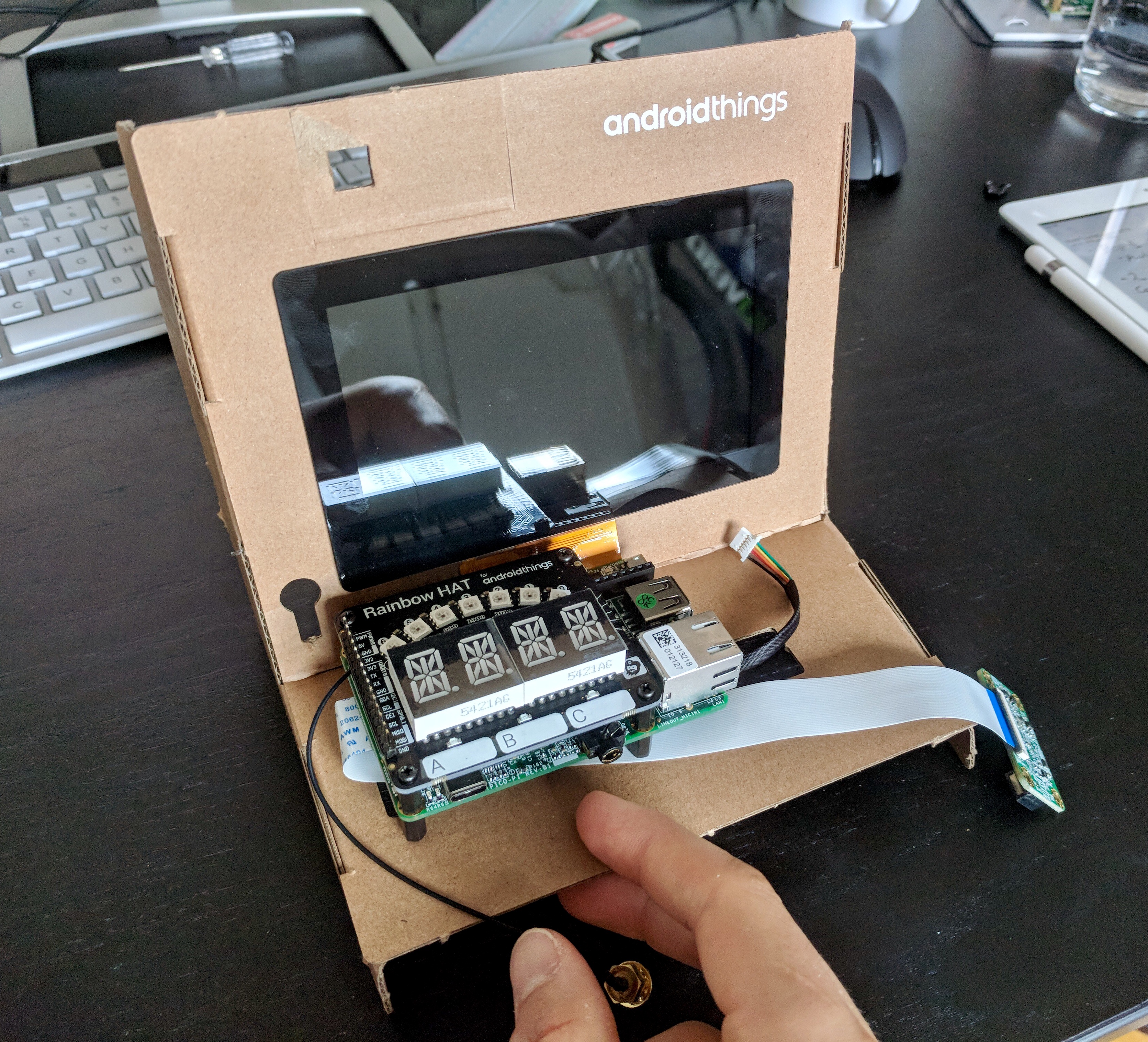
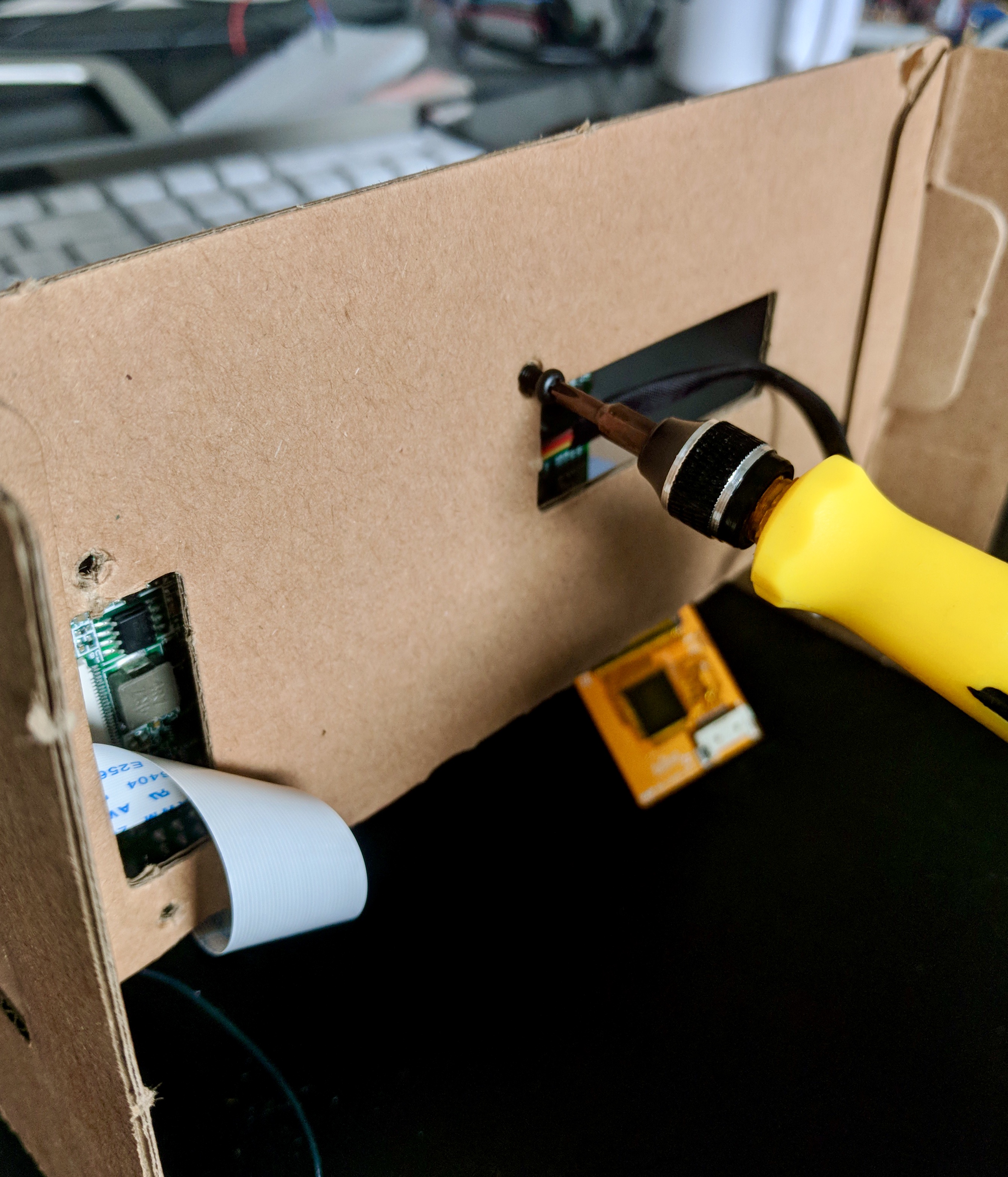
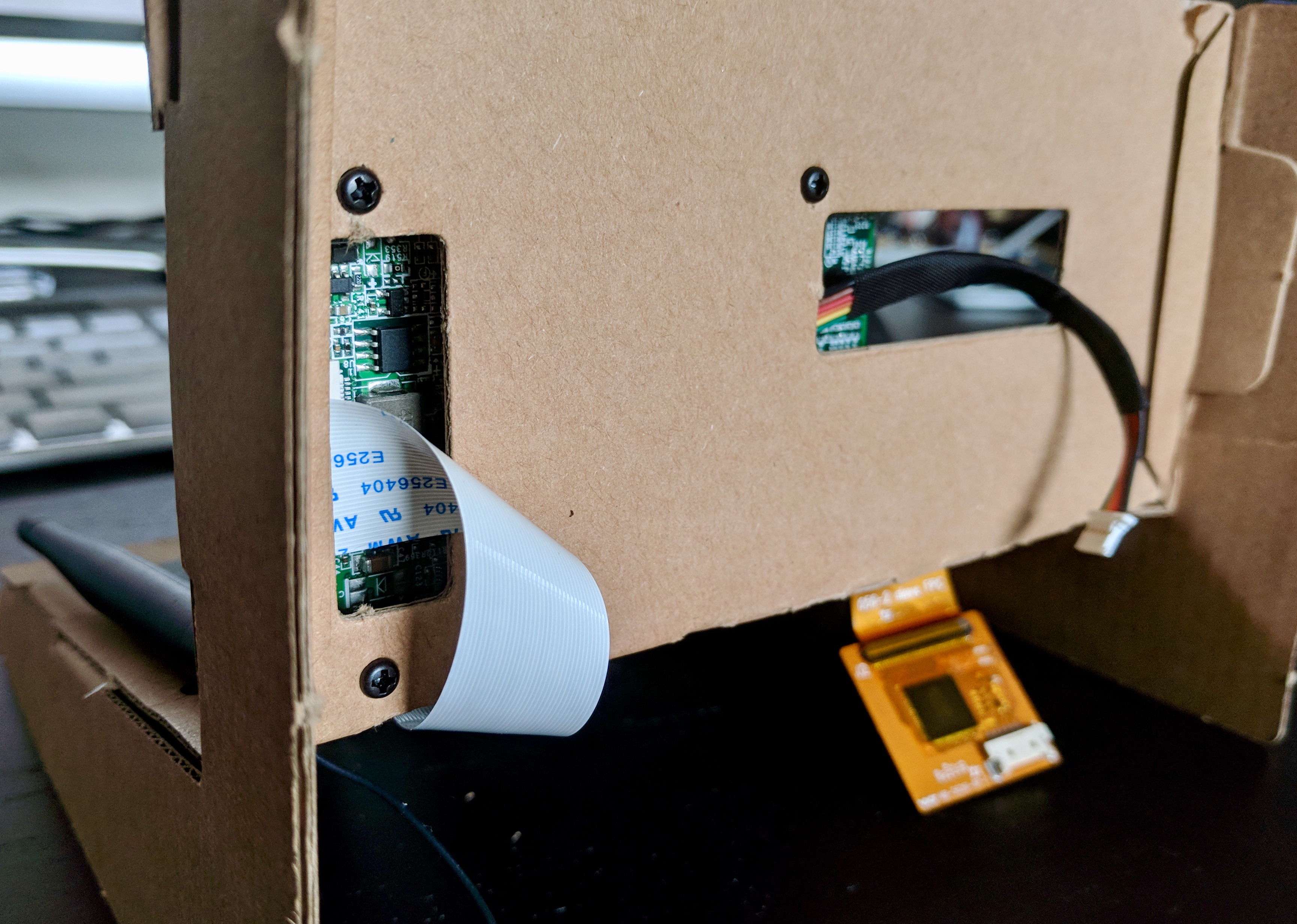
Flip the cardboard frame onto its back now to secure the Dev board to it. There are three pre cut little squares, use the three remaining screws to screw into the three standoffs on the bottom of the board.
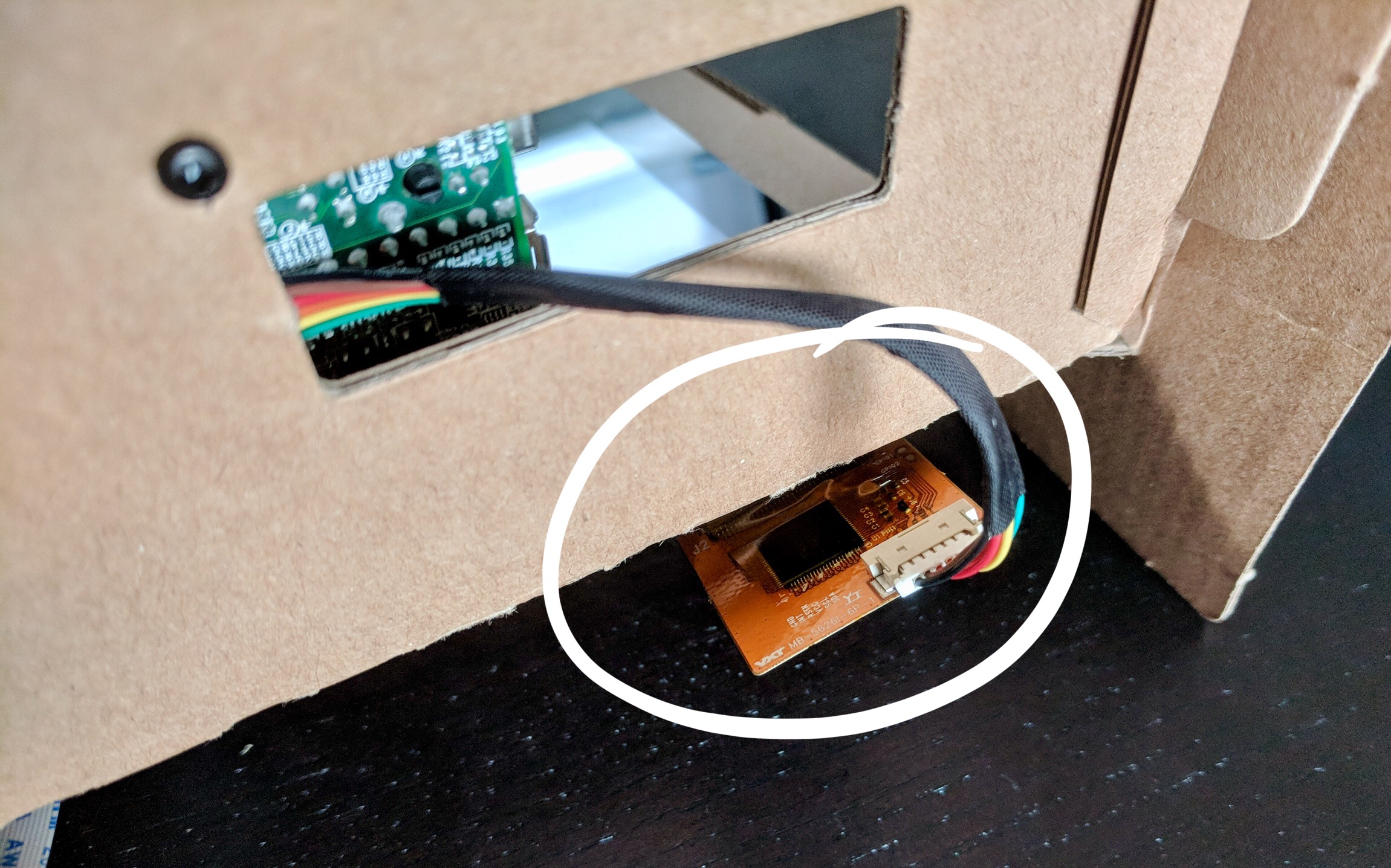
Afterwards it should look like this. Now all that's left is to get rid of that hanging wire.
The last rainbow colored exposed wire gets connected to the hanging display wire, like so:
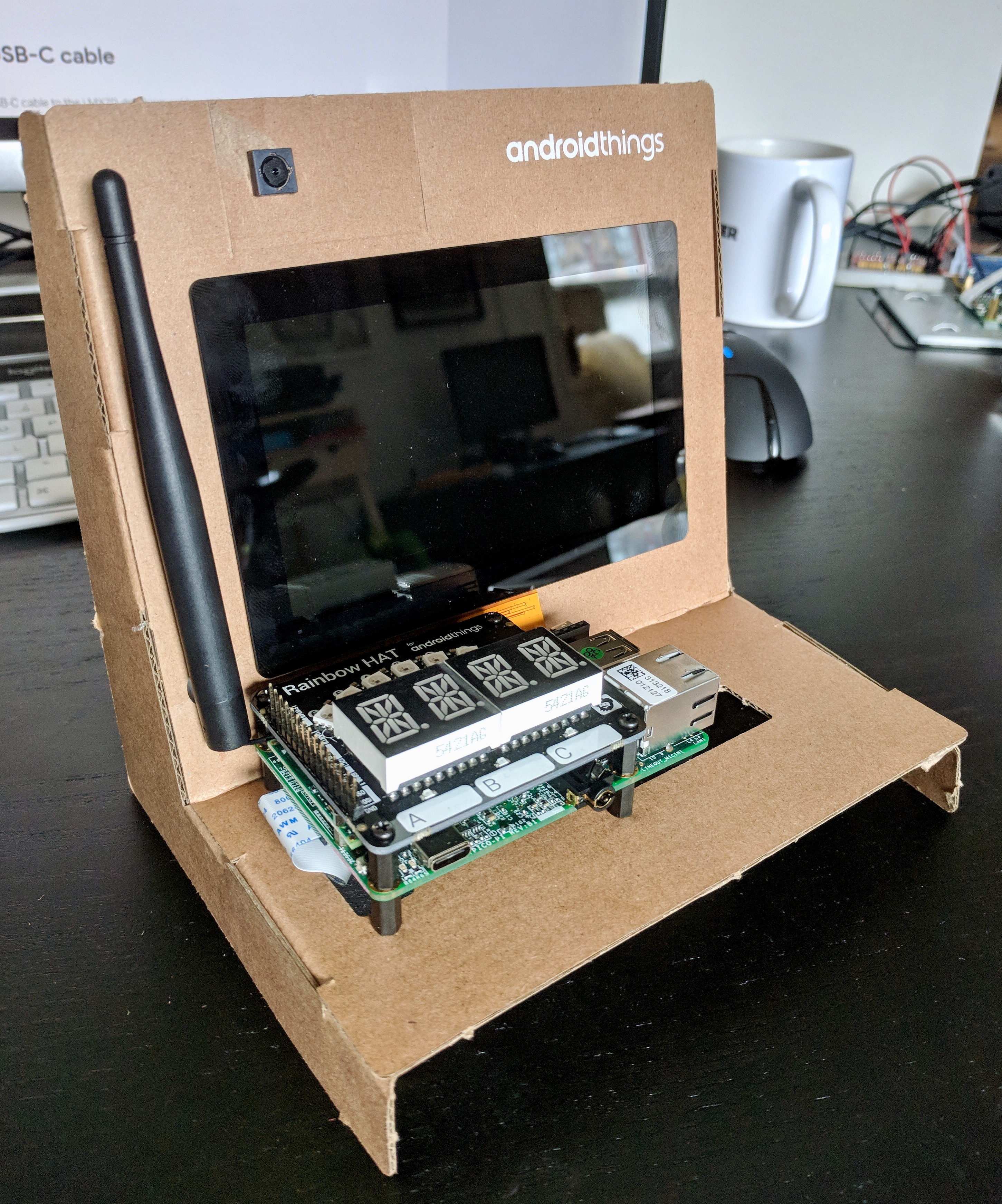
Your android things dev kit is now complete, and should look a little something like the image below.
To turn it on, plug the included usb C cable in just under the 'A' HAT button, and the other end into your computer. You can register your kit using the Android Things Toolkit app for android, or use Google's instructions for updating your device here.
You can test the local peripherals using the touchscreen and running the functions under 'peripherals'. Happy Coding!