A self-balancing robot normally needs a microcontroller. This shows what can be done with a motor and 2 switches.
Introduction: Balancing Robot, With No Microcontroller
A self-balancing robot normally needs a microcontroller to make it work, or more complex electronics such as in the Segway. This one shows what can be accomplished with only a motor, two switches and four batteries.
A video is at the end of this project description.
The basic idea is to move the robot to keep it from falling. This is done in one direction or the other, depending on which way the robot is tilted, fast enough for the tilt to flip to the opposite direction. The robot then moves in that direction, to flip the tilt again. The robot sways back and forth. This is similar to what happens if you try to balance a stick with one end on the palm of your hand. The hand never stays still.
When researching other self-balancing projects, I learned that the robot should not be short and should be top-heavy. This results in slower falling when the robot starts to tilt, and that allows the motor to act quickly enough to stop the falling and to flip the tilt to the opposite direction. I also read that the wheels should not be small.
I considered four methods of accomplishing this project and made three of them. Here is a summary:
1. STORE-BOUGHT TILT SWITCH
Looking for tilt switches on the Internet, I couldn’t find any SPDT (single-pole double-throw) switches. That’s what would be needed in order to have the robot move in one direction or the other, based on its tilt. If two SPST tilt switches were used, I think the tilt angles in this project would be too small for that to work. Also, since the tilt switches have a rolling ball or mercury fluid inside, there could be a possibility of both switches turning on at the same time as the robot moved. This would short out the batteries and they could be ruined or maybe explode. So, I don’t think this method is workable.
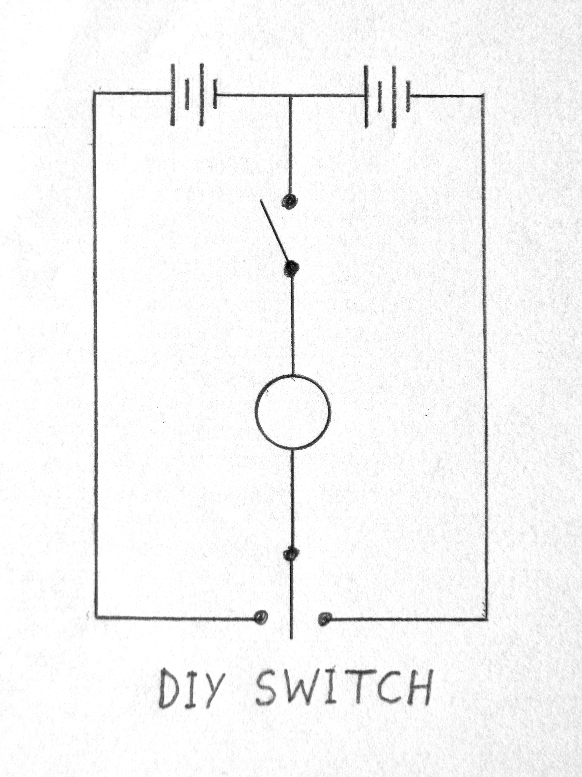
The next idea was to make a tilt switch by hanging a stiff wire from the upper part of the robot and making it touch one of two contacts near the bottom, depending on which way the robot was tilted. I used nails for the contacts and soldered wires to the nails. But this didn’t work as I hoped. The hanging wire didn’t make a good contact reliably.
I tried adding a weight to the hanging wire, hoping it would improve the situation. This almost worked. As soon as the hanging wire made contact, the motor moved the base properly but this sudden movement caused the wire to lose contact and the motor stopped. The robot was still tilted and began to tilt slightly more, and the wire made contact again and the motor activated for an instant again. The result was that the robot was not able to right itself, and I had to use my hand to keep it from falling over.
So, this was almost a great idea but it didn’t work.
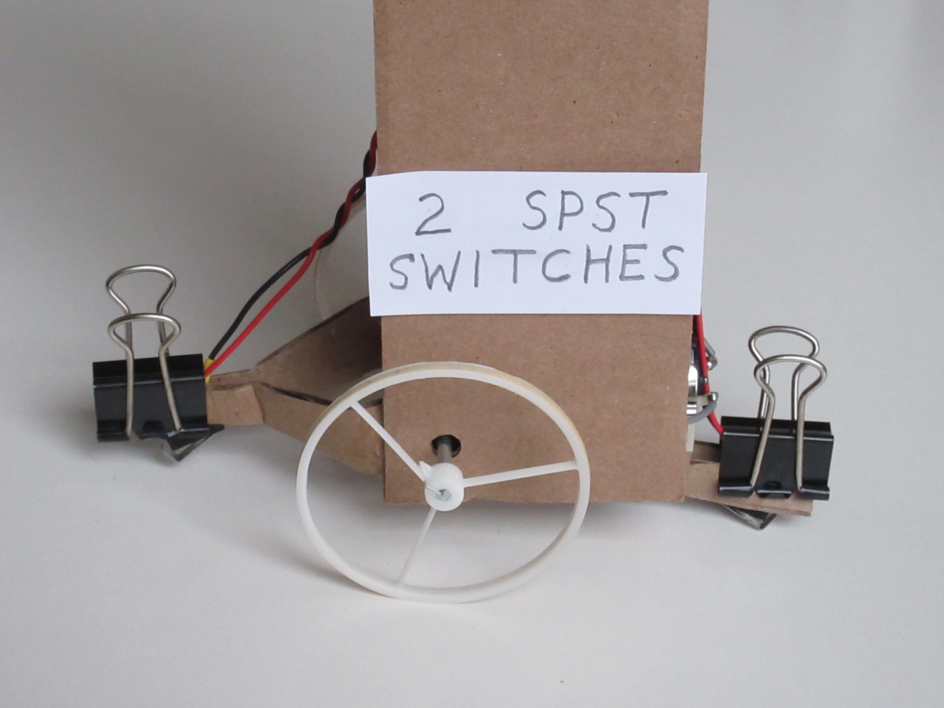
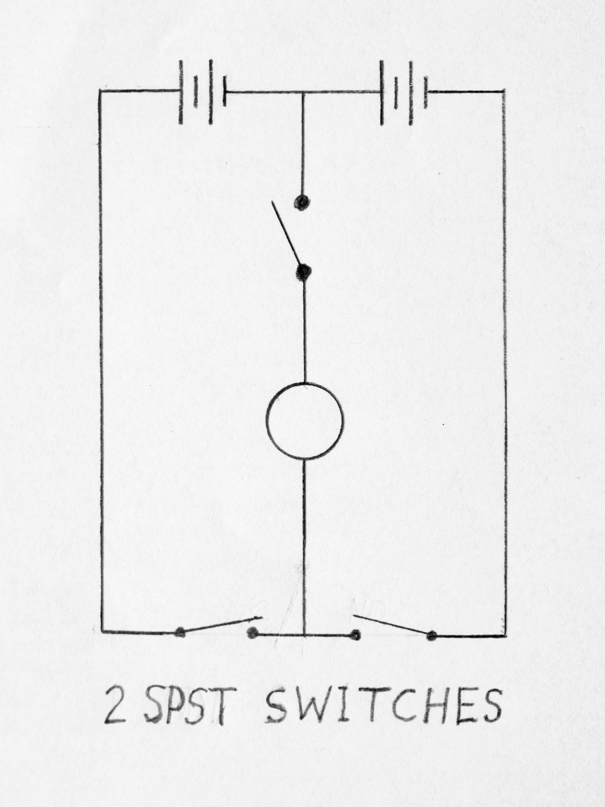
The next thought was to use two SPST (single-pole single-throw) switches located at the bottom of the robot near the floor. One switch would turn on if the robot tilted to one side and the switch touched the floor, and the other switch would turn on if the robot tilted to the other side. Small cardboard pieces, glued to the underside of the robot, held the switches in place as can be seen in the photo at the end of this project description. For experimenting with the up-down placement of the switches, they were held in place by binder clips.
Unfortunately, this idea didn’t work either, no matter how high or low the switches were located. The switches didn’t stay “on” long enough to make the motor flip the tilt to the other side.
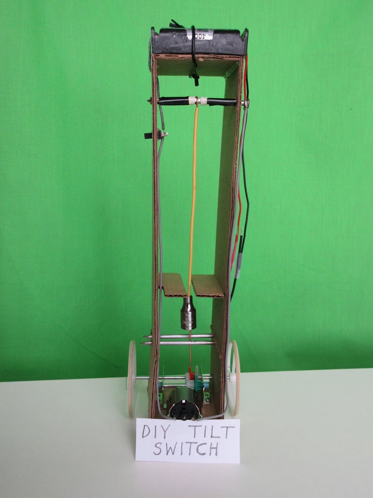
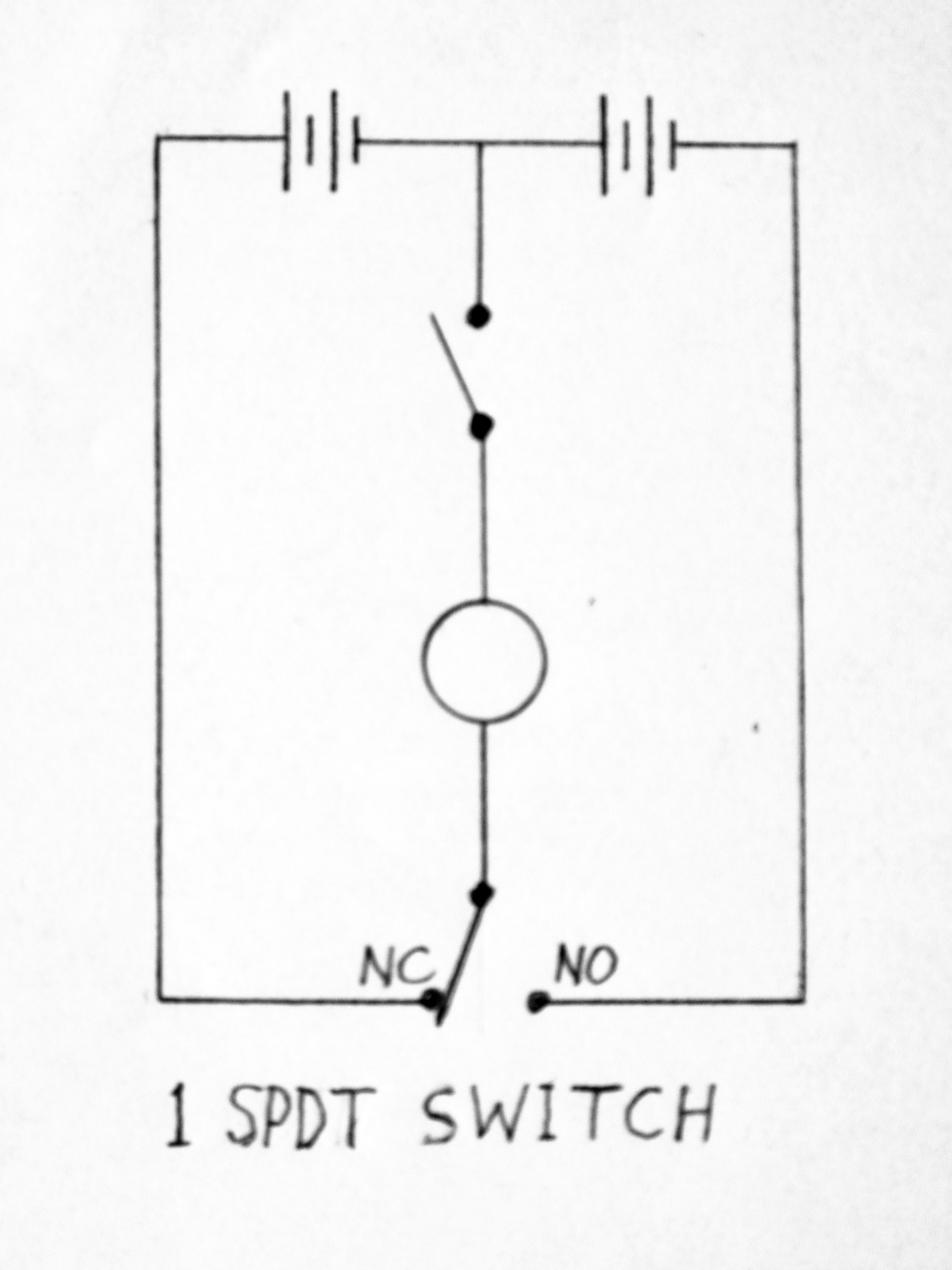
Since the switches didn’t stay “on” long enough in method #3, maybe there’s a way to have a switch keep the motor running in one direction until the tilt flips? That’s the fourth method. A double-throw switch has the motor always running in one direction or the other. The up-down placement of the switch is important. I experimented until it worked well. There is a photo at the end of this project description. For some reason, my robot works well if it is placed down onto the switch after being turned on, but not as well if it is placed onto the wheels. The robot slowly travels in one direction because the motor is “on” longer in that direction than in the other.
This instructable describes the fourth method. There is a video at the end of this project description.
COMMENT: A side-effect of making this very simple robot is that it cannot do anything else. Maybe a circuit could be designed to allow some voice control of the robot to turn left or right, with a microphone, some transistors, and two motors instead of one, but still no microcontroller. I do not have enough knowledge to try to do that.
Supplies
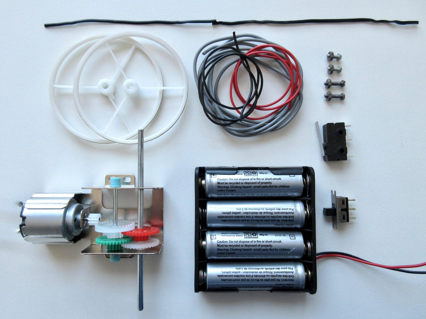
1 x 3 volt motor, about 200 rpm
1 x SPDT (single-pole double-throw) switch with a lever
1 x AA battery holder for 4 batteries or 2 holders for 2 batteries each
Wire to connect the parts
Small bolts and nuts to attach the parts to the body of the robot
Corrugated cardboard or some other stiff cardboard for the body
Twist tie to hold the battery holder in place (or use small bolts)
Soldering iron, solder, etc.
Step 1: Make the Body
When the glue has set well, glue the two halves together to make the robot’s body as shown in the second photo. Again, elastics hold it together until the glue has set.
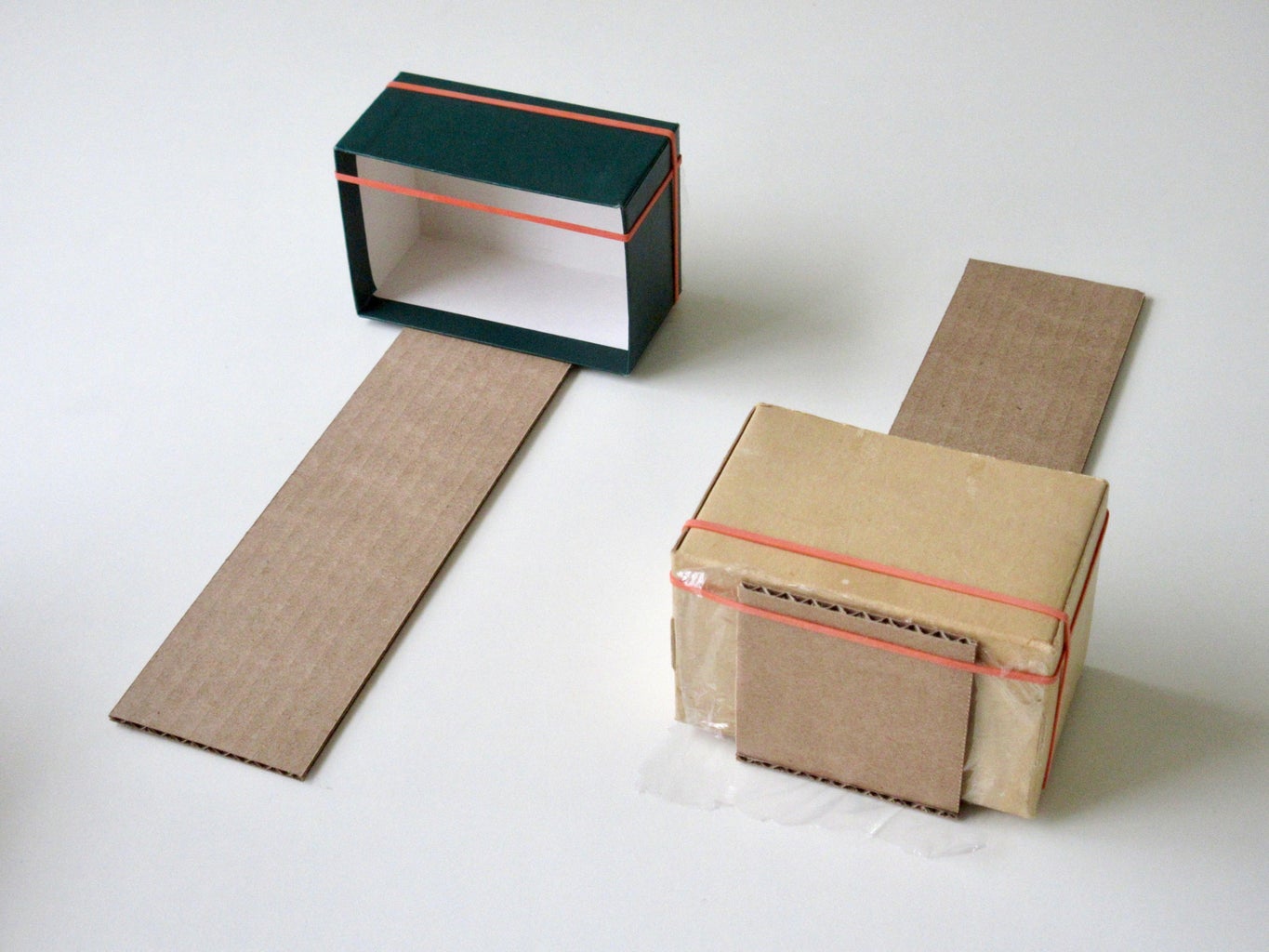
Cut 4 pieces of corrugated cardboard: 2 pieces 10” x 2½” (25 cm x 6.3cm) and 2 pieces 2” x 2½” (5 cm x 6.3cm).
Glue the smaller cardboard pieces to the larger ones as shown in the first photo in this step. The small boxes provide the proper angle, and the elastics hold the cardboard pieces together until the glue sets. There is plastic cling-wrap between the cardboard and the boxes to keep the boxes from becoming glued to the cardboard pieces.
When the glue has set well, glue the two halves together to make the robot’s body as shown in the second photo. Again, elastics hold it together until the glue has set.
Step 2: Attach the Motor
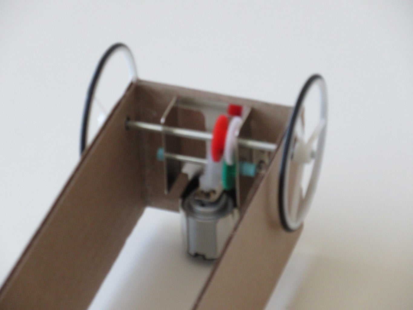
Attach the wheels to the axles.
Place the motor inside one end of the body and cut holes in the sides for the axle to fit through.
Mark where bolts should attach the motor to the body, make small holes there, and attach the motor.
Attach the wheels to the axles.
Step 3: Attach the Battery Holder
Place the battery holder on the outside of the other end of the robot’s body and attach with a twist tie. Or, attach the battery holder first using bolts, and then put the batteries in the holder.
Put the batteries in the battery holder.
Place the battery holder on the outside of the other end of the robot’s body and attach with a twist tie. Or, attach the battery holder first using bolts, and then put the batteries in the holder.
Step 4: Attach the On-Off Switch
Push the switch into the hole. It should hold firmly without any bolts.
Cut a hole in the side of the robot body, a little smaller than the switch.
Push the switch into the hole. It should hold firmly without any bolts.
Step 5: Attach the Lever Switch
Put the lever switch between the longer pieces and use a binder clip to hold the switch during the experimentation of the best up-down location for the switch. Later, the lever switch can be attached with bolts (if you want to do that).
Cut small pieces of cardboard to hold the switch as shown in the photo. The two longer pieces on the outside hold the switch, and the shorter pieces keep the longer ones apart.
Glue these pieces together. An elastic can hold them until the glue sets.
When the glue has set, glue this small thing to the bottom of the robot body. An elastic around the entire robot body can hold it while the glue sets.
Put the lever switch between the longer pieces and use a binder clip to hold the switch during the experimentation of the best up-down location for the switch. Later, the lever switch can be attached with bolts (if you want to do that).
Step 6: Solder the Connections
Cut the wires to the proper length for each connection. I discovered that the wire from the on/off switch to the batteries should be longer, because the proper connection in my battery holder was not at the middle of the batteries. Unexpectedly, it was at one of the side batteries. This was not discovered until I had soldered all the wires (except the wire to the batteries) and tried running the motor. After pushing the wire into the minus spring that should be the middle of the batteries, the motor was fast in one direction but slow in the other. By trial and error, I found that it needs to be pushed into the minus spring of one of the side batteries.
Strip the ends of the wires.
Push the stripped ends into the proper terminals of each part. Twist the stripped red wire from the switch with the stripped red wire of the battery holder, and the same for the black wires. Solder all connections except the motor wires.
The motor must move in the proper direction. To check this (with one wire from the on/off switch pushed into one of the minus springs in the battery holder, and the other wire from the on/off switch and the wire from the lever switch inserted into the motor terminals), turn the robot “on” and check which way the wheels are turning. When the lever switch is “off”, the wheels should move the robot in the direction opposite the switch. And when the lever switch is “on”, the robot should move in the direction where the switch is located. If the wheels are turning in the wrong direction, the wires in the motor terminals need to be reversed.
Solder the wires in the motor terminals.
Step 7: Experiment With Moving the Switch
Place it down on a table onto the switch first and then the wheels. My robot works better if that is done, instead of placing it onto the wheels first.
The robot should sway back and forth, traveling slowly in the direction opposite the switch because the motor is “on” longer in that direction than in the other. If it travels without doing any small tilts backwards, or too long between doing small tilts backwards, turn it off, move the switch slightly higher, and try again.