Power supply unit is an electrical device which converts alternative voltage (AC voltage) to regulated direct voltage (DC voltage) and provide regulated DC power in order to drive a load. The objective of this project is to design and develop a power supply unit which is capable of regulating an AC voltage (with range 15V-25V) to a DC output voltage of 10V and it should be able to withstand a maximum current of 10A. The power supply unit is designed using discrete electronic components without using any programmable integrated circuits.
Introduction
The power supply unit is used to convert an AC voltage to a DC voltage. In this project 230V AC voltage is stepped down using a step down transformer and the stepped down voltage is supplied to the power supply unit as the input.
The circuit mainly consists of 5 sections
1. Full wave rectification
As the power supply unit is fed with ac voltage, first the voltage is full wave rectified. For this a full wave rectification bridge is used with appropriate voltage and current ratings.
2. Smoothing
After rectification a smoothing capacitor is used to smooth the voltage and reduce the ripples.
3. Voltage regulation and feedback
For regulation a Zener diode, an NPN transistor and a variable resistor are used. The circuit regulates the output voltage to a constant voltage which can be controlled by the variable resistor. The transistor provides feedback and controls any fluctuation in the output voltage and maintain a constant output voltage.
4. Current amplification
As the required maximum output current is 10A, the output current is amplified through two transistors. Transistors were selected based on the required current and power ratings.
5. Over current protection
For over current protection a current limiting circuit is implemented using a transistor and a resistor. Based on the power dissipation calculations a resistor with high power rating is used.
Approach
The specifications of the power supply are 10V / 10A. The most challenging aspect of the project was to design the circuit in a way to draw a maximum current of 10A and to maintain a fixed output voltage of 10V across the output irrespective of the load.
This voltage regulator employs the principle of negative feedback to hold the output voltage almost constant despite variations in supply voltage and /or load current. Therefore this regulator is also called a negative feedback regulator.
Input to the power supply is a 15V transformer. Therefore we were required to rectify and smooth the input before passing it through the circuit. There are several practical problems that arise due to dealing with high currents in the circuit such as high voltage drops and high power consumption. As a result of it components with specific power consumption were selected. In order to amplify the current transistors which has a high current rating were used.
Steps of the Project
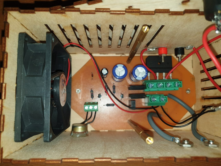
1.Designing and making the PCB
Based on the specifications and requirements few circuit designs were selected.
The designs were then simulated with Multisim software and certain modifications were done according to the issues identified.
Three circuits were chosen and they were presented to the supervisors. The most appropriate design was selected with the help of them and the technical feasibilities, the areas to improve were discussed.
The selected circuit design was analyzed and the components were selected based on the calculations.
After finalizing the circuit design the schematic and layout were designed using Altium software.
After designing the circuits the printed circuit board (PCB) were printed using screen printing techniques.
The PCBs were etched, holes were drilled and the components were mounted and soldered.
Heat sinks were used to dissipate the heat generated from circuit components.
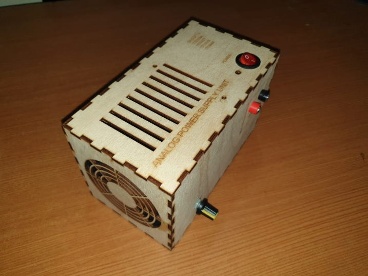
2. Enclosure designing and assembling
An enclosure for the power supply unit was designed using SolidWorks software.
The enclosure was laser cut and assembled.
The selected material was wood.
The PCB was mounted in the enclosure and connectors for input and output were attached to the enclosure.
When designing the enclosure, special consideration was given for cooling methods. Ventilation holes were cut and a cooling fan was connected to dissipate the heat.
A switch and an indication LED was used for indicating power.
3. Testing
The circuit was tested and obtained reading providing an AC input voltage of 15V.
The output voltage and output current were measured for different loads.
Protective Measures
Since we are dealing with high currents in the power supply it is necessary to adapt protective measures to ensure user safety and to prevent the malfunctioning of the power supply.
1. Cooling fan is inserted
Fans are used to draw cooler air into the case from the outside, expel warm air from inside, and move air across a heat sink to cool the transistors and diode bridge.
2.Heat Sinks are used for efficient heat transfer
As a large current pass through the circuit transistors and diode bridge gets heated up. By the inclusion of heat sinks the surface area increases and the heat is distributed effectively
3. Wires with high cross-sectional areas
Since there are high currents passing in the circuit, wires with 2.5mm2 and 1.5mm2 cross-sectional areas are used
4. Enclosure Design
Enclosure is made from plywood which is a good electrical insulator. Ventilation holes are included to enhance an efficient flow of air.
Discussion
Simulation, calculations, circuit diagrams and schematics are included in the resources.